Sign In
Upload
Manuals
Brands
Rohde & Schwarz Manuals
Transceiver
M3SR Series 4100
Rohde & Schwarz M3SR Series 4100 Radio Manuals
Manuals and User Guides for Rohde & Schwarz M3SR Series 4100 Radio. We have
1
Rohde & Schwarz M3SR Series 4100 Radio manual available for free PDF download: Service Manual
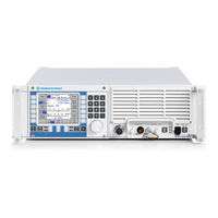
Rohde & Schwarz M3SR Series 4100 Service Manual (138 pages)
Radio Communication Systems. 150 W HF Transceivers
Brand:
Rohde & Schwarz
| Category:
Transceiver
| Size: 34 MB
Table of Contents
Table of Contents
33
1 Description
37
Introduction
37
Fig. 1.1 R&S M3SR Series 4100 150 W HF Transceiver with Optional R&S GB 4000C
37
Comfort Control Unit
37
Construction
38
Fig. 1.2 View of R&S M3SR Series 4100 HF Transceiver Without Cover (Example)
39
Function
40
Function of the R&S M3SR Series 4100 150 W HF Transceiver
40
Function of the Modules
42
Digital Selector - Function
43
Fig. 1.3 Digital Selector, Block Diagram
45
Synthesizer - Function
46
Fig. 1.4 Synthesizer, Block Diagram
48
Frontend - Function
49
Fig. 1.5 Frontend, Block Diagram
50
Radio Controller - Function
51
Fig. 1.6 Radio Controller, Block Diagram
53
Power Amplifier - Function
54
Fig. 1.7 Power Amplifier, Block Diagram
56
Comfort Control Unit (Option) - Function
57
Fig. 1.8 Control Unit R&S GB4000C, Block Diagram
58
Interface Module - Function
59
Fig. 1.9 Interface Module, Block Diagram
59
Front Panel - Function
60
Fig. 1.10 Front Panel
61
Fig. 1.11 Front Panel, Block Diagram
62
Motherboard - Function
63
Fig. 1.12 Motherboard, Block Diagram
66
Antenna Interface - Function
67
Fig. 1.13 Antenna Interface, Mod. 02
67
Fig. 1.14 Antenna Interface, Mod. 03
67
NMEA Interface (Option) - Function
68
Fig. 1.15 R&S GS 4102 NMEA Interface, Block Diagram
69
2 Working Modes and Functions
71
General
71
Voice Communication
71
Data Communication
73
Radio Built-In Test
73
Radio Control
74
Fig. 2.1 GO Leds on Radio Front Panel and on Control Unit
74
Fig. 2.2 Radio with Built-In Control Unit
74
Cable Connections
75
Rear Cabling
75
Fig. 2.3 Rear Cabling
75
Front Cabling
76
Fig. 2.4 Front Cabling
76
3 Test of Equipment Functions
77
Test Equipment and Tools
77
Function Test with Built-In Tests
79
Test of Specification
81
Fig. 3.1 Test Setup
92
4 Troubleshooting
93
Visual Inspection
93
Troubleshooting with Built-In Tests Results
93
Troubleshooting after Testing the Specification
98
Meaning of LED Indications on the Synthesizer
100
5 Replacement of Modules
101
Disassembly
101
General
101
Disassembling the R&S M3SR Series 4100 150 W HF Transceiver
102
Fig. 5.1 Opening the R&S M3SR Series 4100 HF Transceiver (Top)
103
Fig. 5.2 Top View of R&S M3SR Series 4100 Without Cover (Example)
104
Fig. 5.3 Pull-Out Levers
105
Assembly
106
Digital Selector - Removal and Installation
107
Removal of FK 41X0 Digital Selector
107
Fig. 5.4 Removing the FK 41X0 Digital Selector
107
Installation of FK 41X0 Digital Selector
108
Synthesizer - Removal and Installation
109
Removal of Synthesizer (A2)
109
Fig. 5.5 Removing the Synthesizer (A2)
109
Installation of Synthesizer (A2)
110
Frontend - Removal and Installation
111
Removal of Frontend (A1)
111
Installation of Frontend (A1)
112
Fig. 5.6 Removing the Frontend (A1)
112
Radio Controller - Removal and Installation
113
Removal of Radio Controller (A60)
113
Installation of Radio Controller (A60)
114
Fig. 5.7 Removing the Radio Controller (A60)
114
Power Amplifier - Removal and Installation
115
Removal of Power Amplifier (A30)
115
Fig. 5.8 Undoing Screws at the Rear of Power Amplifier (A30)
116
Fig. 5.9 Disconnecting Cables at the Radio Controller (A60)
116
Installation of Power Amplifier (A30)
117
Fig. 5.10 Removing Power Amplifier (A30)
117
R&S GB 4000C - Removal and Installation
118
Removal of R&S GB 4000C Comfort Control Unit
118
Fig. 5.11 Undoing Screws at the R&S GB 4000C Comfort Control Unit
118
Installation of R&S GB 4000C Comfort Control Unit
119
Interface Module - Removal and Installation
120
Removal of Interface Module
120
Installation of Interface Module
121
Fig. 5.12 Removing the Interface Module
121
Front Panel - Removal and Installation
122
Removal of Front Panel (A10)
122
Fig. 5.13 Removing the Front Panel (A10)
122
Installation of Front Panel (A10)
123
Motherboard - Removal and Installation
124
Removal of the Motherboard
124
Fig. 5.14 Disconnecting Cables on Motherboard
125
Fig. 5.15 Fixing Screws at the Transceiver Rear
125
Installation of the Motherboard
126
Fig. 5.16 Removing the Motherboard
126
Antenna Interface - Removal and Installation
127
Removal of the Antenna Interface
127
Installation of the Antenna Interface
127
Fig. 5.17 Removing the Antenna Interface
127
Fans - Removal and Installation
128
Removal of the Fans
128
Installation of the Fans
128
Fig. 5.18 Removing the Fans
128
NMEA Interface - Removal and Installation
129
Removal of the R&S GS 4102 NMEA Interface
129
Installation of the R&S GS 4102 NMEA Interface
129
Fig. 5.19 Removing the R&S GS 4102 NMEA Interface
129
Backup Battery - Removal and Installation
130
Removal of the Backup Battery
130
Installation of the Backup Battery
131
Fig. 5.20 Removing the Backup Battery
131
6 System / Equipment Configuration
133
General
133
Software Update
133
Option Keys
133
A1 Appendix
135
A1.1 Spare Parts
135
Fig. A1.1 Top View of R&S M3SR Series 4100 Without Cover (Example)
136
A1.2 Drawings
137
Advertisement
Advertisement
Related Products
Rohde & Schwarz MNT-BP89WH
Rohde & Schwarz MNT-BP99WH
Rohde & Schwarz MDS-21
Rohde & Schwarz MXO44-243
Rohde & Schwarz MXO44-2415
Rohde & Schwarz MXO4-K550
Rohde & Schwarz MXO4-B6
Rohde & Schwarz MXO4-B1
Rohde & Schwarz MXO 54C
Rohde & Schwarz MXO44
Rohde & Schwarz Categories
Measuring Instruments
Test Equipment
Portable Generator
Power Supply
Accessories
More Rohde & Schwarz Manuals
Login
Sign In
OR
Sign in with Facebook
Sign in with Google
Upload manual
Upload from disk
Upload from URL