Sign In
Upload
Manuals
Brands
Rohde & Schwarz Manuals
Inverter
AMU200A
Rohde & Schwarz AMU200A Manuals
Manuals and User Guides for Rohde & Schwarz AMU200A. We have
2
Rohde & Schwarz AMU200A manuals available for free PDF download: Operating Manual, Application Note
Rohde & Schwarz AMU200A Operating Manual (728 pages)
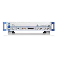
Baseband Signal Generator and Fading Simulator
Brand:
Rohde & Schwarz
| Category:
Test Equipment
| Size: 11 MB
Table of Contents
Table of Contents
20
Preface
32
Documentation Overview
32
Typographical Conventions
33
Notes on Screenshots
34
Preparing for Use
36
Front Panel Tour
36
Utility Keys
37
Standby Leds and Standby Key
37
Display
38
Setup Keys
38
Keys for Setting Parameters
38
Display Keys
39
Keypad for Data Entry
40
Rotary Knob and Navigation Keys
41
Front Panel Connectors
42
Rear Panel Tour
43
Description of the Connectors
44
Putting into Operation
49
EMI Suppression
50
Unpacking and Checking the Instrument
51
Placing or Mounting the Instrument
51
Connecting the Instrument to the AC Supply
53
Starting the Instrument
53
Function Check
54
Start Display and Booting
54
Standby and Ready State
54
Default Settings
55
Shutting down the Instrument
56
Connecting External Accessories
56
Connecting USB Devices
57
Connecting a Monitor
58
Windows Operating System
59
Virus Protection
59
Service Packs and Updates
60
Login
60
Accessing the Start Menu
60
Setting up a Network (LAN) Connection
60
Connecting the Instrument to the Network
61
Assigning the IP Address
62
Using Computer Names
63
Changing the Windows Firewall Settings
63
Working with Directories
64
Remote Access Via an External Controller
65
Using a Web Browser for Remote Access
66
Remote Desktop Connection
67
Remote Access Via a VNC Client Software
70
Using Virus-Protection Software
76
LXI Configuration
77
LXI Browser Settings
79
LAN Configuration
81
IP Configuration
81
Advanced LAN Configuration
82
Ping Client
83
Web Control
84
SCPI Remote Trace
85
Brief Introduction to the Instrument's Concept
88
Getting Started
88
Applications of the Instrument
90
Generation of Digitally Modulated Signals
91
One Path Instrument
93
Two Path Instrument
94
Baseband Section
95
Description of Individual Diagram Blocks of the Baseband Section
97
Example of Setup
99
Key Features
112
Manual Operation
112
Display
117
Settings Displayed in the Header Section
117
Messages
118
Status Information
118
Status Information and Messages
118
Volatile Messages
118
Info Window
119
Permanent Messages
119
Block Diagram
120
Function Blocks in the Block Diagram
121
Signal Flow and Input/Output Symbols in the Block Diagram
121
Structure of the Dialogs
122
Winbar and Softkeys
122
Graphical Display of Output Signal Characteristics
123
Accessing Dialogs
124
Setting Parameters
125
Working with the Cursor
126
Entering a Value
127
Selecting a Control Element
127
Switching Parameters On/Off
127
Working with Units
129
Selecting a Value from a List
130
Terminating Entries with Confirmation
130
Restoring the Previous Value
131
Editors
132
Working with Data Editor
133
Working with Control and Marker List Editor
134
How to Use the Help System
138
File Management
140
File Select Dialog
141
File Manager
143
Extensions for User Files
144
Legend of Front-Panel Controls
146
Front Panel Key Emulation
148
On-Screen Keyboard
148
Instrument Function
150
Overview of Instrument Functions
150
General Instrument Settings
152
Overview of General Instrument Settings
152
Default Instrument Settings - Preset Key
153
General Configuration of Instrument - Setup Key
154
Reference Oscillator
154
Internal Adjustments
157
Hardware Config
159
Software / Options
160
Manage License Keys
161
Display Update
163
Update
163
Check Front Panel
164
Global Trigger/Clock/External Input Settings
165
Display/Keyboard Settings
167
User Marker / aux I/O Settings
168
Remote Channel Settings
172
LXI Status
173
Protection
174
Security
175
Factory Preset
178
Help
178
Save/Recall
178
Switching to Manual Control - Local Key
179
Generating a Hard Copy of the Display
180
Hard Copy Settings
180
Hardcopy Options
181
Help System - Help Key
183
Messages - Info Key
183
Storing and Loading Instrument Data - File Key
184
Save/Recall Menu
185
Storing Instrument Settings
185
Loading Instrument Settings
187
File Select Dialog
189
File Manager
191
Accessing the File System of the Instrument and Transferring Files from and to the Instrument
193
Graphical Display - Graphics
194
Graphics Settings Menu
195
Bar of Graphics Window
198
I/Q Diagram
200
Signal Displays
200
Vector Diagram
201
Constellation Diagram
202
Eye Diagram
203
CCDF Display
204
Power Spectrum
205
Bit and Block Error Rate Measurements - BERT Block
206
PRBS Data
207
Test Setup
207
Clock Signal
208
CRC Polynomial
208
Ending the Measurement
208
Interrupt-Free Measurement
209
Restart Function
209
Data Enable
210
Pattern Ignore
210
Bit Error Rate Menu
211
General Settings
212
Configuration
215
Block Error Rate Menu
219
General Settings
220
Configuration
222
Output of Digital and Analog Baseband Signal - I/Q out
225
Switching I/Q out On/Off
226
Level Display Settings
227
Analog I/Q Output Settings
229
Digital I/Q Output Settings
234
Digital I/Q Output General Settings
235
Sample Rate
235
Signal Output
236
User Variation
237
Power on Settings
238
Signal Monitoring
238
Impairment of Digital I/Q Signal and Noise Generator - AWGN/IMP Block
239
Gain and Gain Imbalance
240
Impairments
240
I and Q Offset
241
Quadrature Offset
241
Impairment Settings Menu
242
AWGN - Noise Generator
243
AWGN Settings Dialog
244
I/Q Level - Info
249
Baseband Signal Level
250
Baseband Signal Power Measurement
251
Baseband Signal - Baseband Block
252
Working with the Baseband Signal
253
Data and Signal Sources in Baseband
259
Internal Modulation Data from Lists
260
Internal PRBS Data and Data Patterns
260
External Synchronous Modulation Data
261
Clock Signals
262
Synchronizing Data Signals and Clock Signals
263
Control Signals
266
Trigger Signals
269
Marker Output Signals
270
Digital Modulation - Custom Digital Modulation
272
Overview and Required Options
272
Modulation Types - Custom Digital Mod
273
Coding - Custom Digital Mod
277
Baseband Filter - Custom Digital Mod
280
Conflicting Settings - Custom Digital Mod
284
Custom Digital Mod User Interface
284
Arbitrary Waveform Generator ARB
313
Introduction
314
ARB User Interface
319
Multi Segment Waveforms
341
Multi Carrier Waveforms
358
Multi Carrier Continuous Wave
371
Multi Carrier CW User Interface
371
External Baseband Signal - Baseband Input
384
Important Signal Parameters
385
Baseband Input Settings Menu
387
BB Input Block
387
Signal Routing and Frequency Shifting
393
Remote Control Basics
398
Remote Control Interfaces and Protocols
398
Messages
399
VISA Libraries
399
LAN Interface
400
Hislip Protocol
402
Protocol
402
Socket Communication
402
GPIB Interface (IEC/IEEE Bus Interface)
403
LAN Interface Messages
403
GPIB Interface Messages
404
GPIB Instrument Address
405
LXI Browser Interface
405
Starting a Remote Control Session
405
Switching to Remote Control
406
Returning to Manual Operation
407
Examples
408
Remote Control over GPIB
408
Remote Control over LAN Using VXI-11 Protocol
409
Remote Control over LAN Using Socket Communication
414
SCPI Command Structure
421
Syntax for Common Commands
421
Syntax for Device-Specific Commands
422
SCPI Parameters
424
Overview of Syntax Elements
427
Structure of a Command Line
427
Responses to Queries
428
Command Sequence and Synchronization
429
Preventing Overlapping Execution
431
Status Reporting System
432
Hierarchy of the Status Registers
433
Structure of a SCPI Status Register
434
Status Byte (STB) and Service Request Enable Register (SRE)
436
Event Status Register (ESR) and Event Status Enable Register (ESE)
437
Operation Status Register (Status:operation)
438
Questionable Status Register (Status:questionable)
438
Application of the Status Reporting System
439
Serial Poll
439
Service Request
439
Error Queue
440
Query of an Instrument Status
440
Reset Values of the Status Reporting System
440
General Programming Recommendations
441
Common Commands
442
Conventions Used in SCPI Command Descriptions
442
Remote Control Commands
442
Usage
443
Cls
443
Ese
443
Esr
443
Idn
444
Ist
444
Opc
444
Opt
444
Pre
445
Psc
445
Rcl
445
Rst
445
Sav
446
Sre
446
Stb
446
Trg
446
Tst
446
Preset Commands
447
Wai
447
Tag Description
449
Waveform and List Format
449
{Type: Magic, XXXXXXXX}
450
TYPE: Magic, XXXXXXXX
450
CLOCK: Frequency
451
COMMENT: String
451
COPYRIGHT: String
452
DATA BITLENGTH: Bitlength
452
DATA LIST-Length: #D0D1
452
DATE: Yyyy-MM-DD;Hh:MM:ss
453
EMPTYTAG-Length: #Emptysequence
453
CONTROL LENGTH: Controllength
454
LEVEL OFFS: Rmsoffset_Db,Peakoffset_Db
455
SAMPLES: Samples
456
[TRACE] LIST [#]: Pos0:State0; Pos1:State1
456
WAVEFORM-Length: #I0Q0I1Q1
457
MWV_SEGMENT_COUNT: Numofseg
458
MWV_SEGMENT_CLOCK_MODE: Mode
459
MWV_SEGMENT_LENGTH: Samplesseg0, Samplesseg1
459
Mwv_Segment_Start
459
Samplestartoffsetseg0, Samplestartoffsetseg1
459
MWV_SEGMENT_CLOCK: Clockseg0, Clockseg1
460
CONTROL LIST WIDTH4-Length: #M0M1
461
Filenameseg0.Wv", "Filenameseg1.Wv
461
Mwv_Segmentx_Comment: Text
461
Mwv_Segment_Files
461
Mwv_Segment_Level_Offs
461
Rmsoffs_Dbsg0,Peakoffs_Dbsg0
461
How to Define Periodically Repeating Traces
462
How to Manually Create a Waveform Using Tag File Format
464
Creating an ASCII C-List Manually
468
BERT and BLER Subsystems
470
Editing Waveform Files, Data and Control Lists
470
Bler:result? :Bert:result?
471
Bert:setup:denable
474
Bler:setup:denable
474
Bert:setup:ignore
475
Bert:setup:mcount
476
Bert:setup:merror
476
Bert:setup:restart[:State]
476
Bler:setup:mcount
476
Bler:setup:merror
476
Bert:setup:timeout
477
Bert:setup:type
477
Bert:start
477
Bler:setup:timeout
477
Bler:setup:type
477
Bler:start
477
Bert:state
478
Bert:stop
478
Bler:state
478
Bler:stop
478
Bert:unit
479
Bler:unit
479
[:Source]:Input:bert:impedance
479
[:Source]:Input:bert:threshold
479
Calibration Subsystem
480
Trigger:bert[:Immediate]
480
Trigger:bler[:Immediate]
480
Clock Subsystem
482
Diagnostic Subsystem
483
Display Subsystem
485
Format Subsystem
488
Hcopy Subsystem
490
Hcopy:device:language
491
Hcopy:file[:Name]
492
Hcopy:file[:Name]:Auto
492
Hcopy:file[:Name]:Auto:directory
492
Hcopy:file[:Name]:Auto:directory:clear
493
Hcopy:file[:Name]:Auto:file
493
Hcopy:file[:Name]:Auto[:File]:Day
493
Hcopy:file[:Name]:Auto[:File]:Month
494
Hcopy:file[:Name]:Auto[:File]:Number
495
Hcopy:file[:Name]:Auto[:File]:Prefix
495
Hcopy:file[:Name]:Auto[:File]:Prefix:state :Hcopy:file[:Name]:Auto[:File]:Year
496
Hcopy:image:format
496
Hcopy:image:size
497
Hcopy:printer:color[:State]
497
Hcopy:printer:list
497
Hcopy:printer:page:margins
498
Hcopy:printer[:Name]
498
Kboard Subsystem
499
File Naming Conventions
500
Mmemory Subsystem
500
Extensions for User Files
501
Examples
503
Remote Control Commands
505
Output Subsystem
511
Source Subsystem
512
Source:awgn Subsystem
512
Source:bb Subsystem
521
Source:bb Subsystem General Commands
521
Source:bb:arb Subsystem
523
[:Source<Hw>]:Bb:arbitrary:preset/[:Source<Hw>]:Bb:arbitrary:state
524
[:Source<Hw>]:Bb:arbitrary:clock
524
[:Source<Hw>]:Bb:arbitrary:preset
524
[:Source<Hw>]:Bb:arbitrary:state
524
[:Source<Hw>]:Bb:arbitrary:clock:mode
525
[:Source<Hw>]:Bb:arbitrary:clock:multiplier
525
[:Source<Hw>]:Bb:arbitrary:clock:source
526
Source:bb:arb:mcar Subsystem
541
Source:bb:arb:wav Subsystem
556
Source:bb:arb:wseg Subsystem
562
Bb:arb:wseg:seq:sel 'D:\User\Play_List_1'
573
Common Settings
573
Source:bb:DM Subsystem
573
The Following Section Contains the Commands for Generating the Digital Modulation Sig- Nal. Common Settings
573
[:Source<Hw>]:Bb:DM:pattern
573
Usage: Event
574
[:Source<Hw>]:Bb:DM:prbs[:Length]
574
[:Source<Hw>]:Bb:DM:preset
574
[:Source<Hw>]:Bb:DM:source
574
[:Source<Hw>]:Bb:DM:srate
575
Manual Operation: See
576
Parameters: <State
576
[:Source<Hw>]:Bb:DM:standard
576
[:Source<Hw>]:Bb:DM:state
576
[:Source<Hw>]:Bb:DM:switching:source
576
| off | on
576
Clock Settings
577
[:Source<Hw>]:Bb:DM:switching:state
577
Trigger Settings
579
Marker Settings
588
Filter Settings
590
Modulation Settings
594
Power Ramp
597
Source:bb:graphics Subsystem
612
Source:bb:impairment Subsystem
615
Source:bb:mccw Subsystem
617
Source:bb:measurement Subsystem
638
Source:bb:power Subsystem
642
Source:bb:progress Subsystem General Commands
643
Advertisement
Rohde & Schwarz AMU200A Application Note (23 pages)
Brand:
Rohde & Schwarz
| Category:
Inverter
| Size: 1 MB
Table of Contents
Table of Contents
2
1 Introduction
3
2 Functional Description
4
3 Setup
5
Providing WLAN Access for the T&M Instrument
6
WLAN Connection Via WLAN Router
6
WLAN Connection Via WLAN USB Adapter
7
Installation for Windows XP T&M Instruments
8
Installation for Windows 7 T&M Instruments
11
Installing the RDP Client Application on the Tablet
13
Establishing the WLAN Connection on the Tablet
13
Establishing the RDP Connection
14
4 Operation
17
Locking the Tablet's Screen Rotation Function
17
Controlling the T&M Instrument Via RDP
17
Operation Via Virtual Mouse and Keyboard
17
Control Elements of the T&M Instrument Views
18
Starting a Firmware Application on a CMW
20
Disconnecting from the T&M Instrument
20
5 Related Documents
22
6 References
22
Advertisement
Related Products
Rohde & Schwarz AFQ100B
Rohde & Schwarz AREG100A
Rohde & Schwarz AMU-K48
Rohde & Schwarz AMU-K52
Rohde&Schwarz Smart Instruments AM300
Rohde & Schwarz R&S AMS32-K31
Rohde & Schwarz AMN6500
Rohde & Schwarz AMN6500-D
Rohde & Schwarz AMN6500-UK
Rohde & Schwarz AMN6500-US
Rohde & Schwarz Categories
Measuring Instruments
Test Equipment
Portable Generator
Power Supply
Accessories
More Rohde & Schwarz Manuals
Login
Sign In
OR
Sign in with Facebook
Sign in with Google
Upload manual
Upload from disk
Upload from URL