Sign In
Upload
Manuals
Brands
Rohde & Schwarz Manuals
Receiver
6162.4644.02
Rohde & Schwarz 6162.4644.02 Manuals
Manuals and User Guides for Rohde & Schwarz 6162.4644.02. We have
1
Rohde & Schwarz 6162.4644.02 manual available for free PDF download: Operating Manual
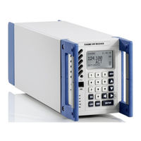
Rohde & Schwarz 6162.4644.02 Operating Manual (189 pages)
VHF Compact Receiver
Brand:
Rohde & Schwarz
| Category:
Receiver
| Size: 18 MB
Table of Contents
Table of Contents
5
1 User Information
26
General Features
28
Explanation of a Model
28
Required Personnel
29
Required Power Supply
29
Design
30
Functioning
31
Block Diagram
31
Fig. 1.2 Block Diagram
31
Functions Description
32
General Data
33
Accessories
33
Storage
33
2 Preparation for Use
34
Safety Precautions
34
Unpacking and Checking
35
Installation into a 19" Rack
36
Installation of Two Radios
36
Fig. 2.1 Installation of Two Radios
36
Installation with Blank Panel
37
Basis Cabling
38
Rear Cabling
38
Fig. 2.3 Rear Cabling
39
Front Cabling
41
Fig. 2.4 Front Cabling
41
Switching On/Off
42
Mechanical Interface Description
42
Function Test
43
3 Operation
44
Control Elements and Interfaces
45
Front View
45
Fig. 3.1 Front View
45
Rear View
46
Fig. 3.2 Rear View
46
Introduction
47
Control Interfaces
47
Modes of Control
48
Non-Controlled Mode
48
Fig. 3.3 Non-Controlled Mode
48
Remote Mode
49
Local Mode
50
Fig. 3.5 Local Mode
50
Service Mode
51
Fig. 3.6 Service Mode
51
Configuring with the R&S ZS 4200
52
Factory Default Settings
52
Meaning of Parameters
57
CBIT Type Configuration
67
Local Control (Local Mode)
67
Overview of Operation
68
Fig. 3.7 Overview of Operation
68
Making Entries from the Keypad
69
Numeric Keys
69
Cursor Keys
69
Fig. 3.8 Keypad
69
MENU Key
70
ENTER Key
70
ESC Key
70
SQ Key
71
Fig. 3.9 Squelch Behavior
72
LOC Key
73
Screen Display
74
Start Display
74
Boot Display
74
Fig. 3.10 R&S Series 4200 Logo
74
Fig. 3.11 Boot Display
74
Standard Operating Display
75
Main Menu Display
76
Display Settings and Volume Control
77
Indication Via Leds
79
Fig. 3.17 Indication Via Leds
79
Calling and Changing Menus
80
Setting Parameters
82
Toggling a Setting
82
Fig. 3.20 Toggling a Setting
82
Selecting Settings
83
Fig. 3.21 Selecting Settings
83
Entering Numeric Parameters
84
Fig. 3.22 Frequency Entry
85
Overview of All Menus and Functions
86
MAIN Menu
86
Fig. 3.23 MAIN Menu
86
OPERATION Menu
87
Fig. 3.25 ICAO Channeling / Frequency Pairing
88
Fig. 3.27 Supported Frequency Ranges
89
TIME/DATE Menu
90
MEASUREMENT Menu
90
Fig. 3.28 TIME / DATE Menu
90
Fig. 3.29 MEASUREMENT Menu
90
RX PARAMETER Menu
91
SUPPLY Menu
91
Fig. 3.30 RX PARAMETER Menu
91
Fig. 3.31 SUPPLY Menu
91
TEMPERATURE Menu
92
OPERATING HOURS Menu
92
Fig. 3.32 TEMPERATURE Menu
92
Fig. 3.33 OPERATING HOURS Menu
92
CBIT STATUS Menu
93
Fig. 3.34 CBIT STATUS Menu
93
INVENTORY Menu
95
Fig. 3.36 INVENTORY Menu
95
Fig. 3.37 INVENTORY Menu: Display Format
96
CONFIGURATION Menu
97
IP ADDRESS Menu
97
Fig. 3.38 CONFIGURATION Menu
97
Fig. 3.39 IP ADDRESS Menu
98
Fig. 3.47 Ipv6 Gate Address Setting
102
FREQUENCY BLOCK Menu
103
Fig. 3.48 Indication of Frequency Blocking Ranges
103
DISPLAY SETTINGS Menu
104
RX THRESHOLDS Menu
107
OPTIONS Menu
109
AUDIO DELAY Menu
110
AUDIO INTERFACE Menu
111
Remote Control (Remote Mode) Via LAN
112
Fig. 3.61 Radio Control Via LAN
112
Main/Standby Operation (1:1) in Analog and Voip Mode
113
Introduction/Overview
113
Fig. 3.62 Receiver in Main/Standby Configuration
114
Behavior of the Main/Standby Configuration with Power on
115
Fig. 3.63 Active Device
115
Fig. 3.64 Inactive Device
115
Behavior at Remote Control
116
Fig. 3.65 Device in Local Mode (LOC) Activation State on
116
Fig. 3.66 Device in Remote Control Mode Activation State AUTO
116
Behavior in Case of Device Errors
117
Behaviour in Voip Mode
117
Cabling (Analog)
118
Configuration
118
Cabling (Voip)
119
Fig. 3.69 Main/Standby Cabling in Voip Mode
120
Limitations/Notes
121
External Automatic Filters
122
Telsa External Automatic Filter
122
Introduction/Overview
122
Cabling
122
Fig. 3.70 Telsa External Automatic Filter Connection
122
Configuration
123
Limitations/Notes
123
R&S External Automatic Filter
123
Introduction/Overview
123
Cabling
124
Configuration
124
Limitations/Notes
124
External Automatic Filters with R&S Protocol
125
Cabling
125
Fig. 3.72 External Automatic Filter with R&S Protocol Connection
125
Configuration
128
In-Band Signaling of SQ with Different Audio Tones
128
Audio In-Band Tones for RSSI Signaling
128
In-Band Signaling of STD with Different Audio Tones
128
RSSI Output Characteristic
129
Introduction/Overview
129
Fig. 3.74 RSSI Output Type − R&S Standard
129
Configuration
130
Limitations/Notes
131
ACARS Mode (External Modem)
131
Introduction/Overview
131
Cabling
131
Fig. 3.76 ACARS Mode Cabling
131
Configuration
132
Limitations/Notes
133
Best Signal Selection
134
Introduction/Overview
134
Fig. 3.79 Radio 1 Has a Stronger Receive Signal, no Switchover Audio Signal
134
Cabling
135
Fig. 3.80 Radio 2 Receives a Stronger Signal, Audio Signal Is Switched from Radio 1 to
135
Configuration
136
Limitations/Notes
136
Audio Via E1 Interface (Optional)
137
Introduction/Overview
137
Cabling
138
Configuration
138
Limitations/Notes
139
Parallel Operation of the Analog and E1 Audio Interfaces
139
Radio in VDL Mode 2
140
Introduction/Overview
140
Cabling
140
Configuration
141
Limitations/Notes
142
Audio Via Voip (Optional)
143
Introduction/Overview
143
Cabling
144
Configuration
144
Limitations/Notes
144
Fig. 3.86 Voip Cabling
144
Voip Information on Standard Operation Screen
145
Voip Connections
146
Fig. 3.87 Voip Connections
146
Voip Connection Establishment
147
AM Voice Functionality with Voip Interface
148
Parallel Operation of the Analog and Voip Audio Interfaces
148
Simultaneous Transmission Detection (Optional)
149
Channel Scanning Function (Optional)
150
Software Download
152
4 Malfunction
154
Visual Inspection
154
Cabling Check
154
Checking the LED State
155
Checking the CBIT State
156
Troubleshooting
157
RX CBIT Events
157
Unexpected Radio Restart
164
Fig. 4.3 Validation Result Mask
167
5 Maintenance
168
Scheduled Maintenance
168
Fan Maintenance
170
Cleaning
171
6 Technical Information
172
Specifications
172
Interface Description
172
AC Input X1
172
Fig. 6.1 AC Input X1
172
DC Input/Battery Input X2
173
Fig. 6.2 DC Input/Battery Input X2
173
RX Input X8
174
Fig. 6.3 RX Input X8
174
Ethernet - LAN Remote Control X9
175
RX Audio Basic X10
176
Fig. 6.5 RX Audio Basic X10
176
RX Audio Extended X11
177
Fig. 6.6 RX Audio Extended X11
177
Host Interface Port X12 (Reserved)
179
Fig. 6.7 RS-422 - Host Interface Port X12 (Reserved)
179
RX E1 - Communication Data Connector X13
180
USB Device Connector X20
181
Headphone Connector X23
181
Remote Control Commands
182
7 Index
184
8 Appendix
188
Advertisement
Advertisement
Related Products
Rohde & Schwarz 6162.4521.02
Rohde & Schwarz 6144.7800.02
Rohde & Schwarz 6144.7800.12
Rohde & Schwarz 6174.7620.02
Rohde & Schwarz 6174.7689.02
Rohde & Schwarz 6174.7720.02
Rohde & Schwarz 6164.7092.02
Rohde & Schwarz CLIPSTER 6 Mk2
Rohde & Schwarz 1142.8007.03
Rohde & Schwarz 1142.8007.07
Rohde & Schwarz Categories
Measuring Instruments
Test Equipment
Portable Generator
Power Supply
Accessories
More Rohde & Schwarz Manuals
Login
Sign In
OR
Sign in with Facebook
Sign in with Google
Upload manual
Upload from disk
Upload from URL