Sign In
Upload
Manuals
Brands
Rohde & Schwarz Manuals
Laboratory Equipment
1407.6004K02
Rohde & Schwarz 1407.6004K02 Manuals
Manuals and User Guides for Rohde & Schwarz 1407.6004K02. We have
1
Rohde & Schwarz 1407.6004K02 manual available for free PDF download: Operating Manual
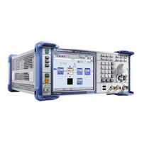
Rohde & Schwarz 1407.6004K02 Operating Manual (911 pages)
Vector Signal Generator
Brand:
Rohde & Schwarz
| Category:
Portable Generator
| Size: 13 MB
Table of Contents
Table of Contents
18
Customer Support
17
Sensor Assignment Read<Ch> and Iniate<Hw>; Range: [1] to
19
1 Preface
32
Documentation Overview
32
For Your Safety
32
Operating Manual and Help
32
Quick Start Guide Manual
32
Basic Safety Instructions
33
Data Sheets and Brochures
33
Instrument Security Procedures
33
Service Manual
33
Application Notes, Application Cards, White Papers, Etc
34
Notes on Screenshots
34
Front Panel Tour
35
Release Notes and Open Source Acknowledgment (OSA)
34
Keys for Setting Parameters
39
Display Keys
40
Sensor Mapping List: Element<Ch>; Range [1] to
40
Keypad for Data Entry
41
Front Panel Connectors
42
Rotary Knob and Navigation Keys
42
Rear Panel Tour
43
Description of the Connectors
44
Putting into Operation
47
EMI Suppression
48
Placing or Mounting the Instrument
49
Unpacking and Checking the Instrument
49
Connecting the Instrument to the AC Supply
51
Starting the Instrument
51
Function Check
52
Standby and Ready State
52
Start Display and Booting
52
Default Settings
53
Shutting down the Instrument
54
Connecting External Accessories
55
Connecting USB Devices
55
Power Fuses
55
Linux Operating System
56
Connecting the Instrument to the Network
58
Setting up a Network (LAN) Connection
58
Assigning the IP Address
59
Using Computer Names
60
Remote Access Via an External Controller
61
Using a Web Browser for Remote Access
62
Remote Access Via a VNC Client Software
64
LXI Configuration
68
LXI Browser Settings
69
LAN Configuration
71
IP Configuration
71
Advanced LAN Configuration
72
Ping Client
73
Web Control
74
SCPI Remote Trace
75
2 Preparing for Use
35
Utility Keys
36
Display
37
Standby Leds and Standby Key
37
Setup Keys
39
3 Getting Started
78
Brief Introduction to the Instrument's Concept
78
Baseband Section
80
Description of Individual Diagram Blocks of the Baseband Section
82
RF Section
83
Description of Individual Diagram Blocks of the RF Section
83
Example of Setup
84
Key Features
91
Display
96
4 Manual Operation
91
Settings Displayed in the Header Section
97
Messages
98
Status Information
98
Status Information and Messages
98
Volatile Messages
98
Permanent Messages
99
Info Window
99
Block Diagram
100
Function Blocks in the Block Diagram
100
Signal Flow and Input/Output Symbols in the Block Diagram
101
Structure of the Dialogs
102
Winbar and Softkeys
102
Graphical Display of Output Signal Characteristics
103
Accessing Dialogs
104
Setting Parameters
105
Working with the Cursor
106
Entering a Value
107
Selecting a Control Element
107
Switching Parameters On/Off
107
Working with Units
109
Selecting a Value from a List
110
Terminating Entries with Confirmation
110
Restoring the Previous Value
111
Editors
112
Working with List Editor
112
Working with Data Editor
114
Working with Control and Marker List Editor
115
How to Use the Help System
119
File Management
120
File Select Dialog
122
File Manager
123
Extensions for User Files
124
Legend of Front-Panel Controls
127
Front Panel Key Emulation
128
Default Instrument Settings - Preset Key
133
Overview of General Instrument Settings
133
General Configuration of Instrument - Setup Key
134
Internal Adjustments
135
Hardware Config
137
Software / Options
138
Manage License Keys
139
NRP-Z Info/Update
144
Delete Temporary Files
146
Display Update
147
Selftest
147
Check Front Panel
148
5 Instrument Function
130
Overview of Instrument Functions
130
General Instrument Settings
133
Date and Time
150
Shutting down and Rebooting the Instrument
150
Network Settings
151
Global Trigger/Clock/External Input Settings
154
Display/Keyboard Settings
157
Remote Channel Settings
158
Instrument Emulations
159
Protection
161
Security
162
Save/Recall
168
Factory Preset
169
Help
169
Switching to Manual Control - Local Key
169
Generating a Hard Copy of the Display
170
Hard Copy Options
171
Hard Copy Settings
171
Help System - Help Key
173
Messages - Info Key
173
Storing and Loading Instrument Data - File Key
174
Save/Recall Menu
175
Saving Instrument Settings
176
Loading Instrument Settings
177
File Select Dialog
179
File Manager
181
Map Network Share Settings
183
Mapping a Network Folder
184
Accessing the File System of the Instrument and Transferring Files from and to the Instrument
186
Instrument
186
Graphical Display - Graphics
189
Graphics Settings Menu
190
Bar of Graphics Window
192
I/Q Diagram
194
Signal Displays
194
Vector Diagram
195
Constellation Diagram
196
Eye Diagram
196
CCDF Display
197
Power Spectrum
197
Bit and Block Error Rate Measurements
198
Test Setup
198
PRBS Data
199
Clock Signal
200
CRC Polynomial
200
Ending the Measurement
200
Interrupt-Free Measurement
201
Restart Function
201
Data Enable
202
Pattern Ignore
202
Bit Error Rate Settings
203
General Settings
204
Configuration Settings
206
Block Error Rate Settings
211
General Settings
211
Configuration Settings
214
Connector Settings
216
Test Generator
217
Test Generator Setup
218
Test Generator Settings
219
BER/BLER Functionality Test
221
Overview of RF Signal
222
RF Block
222
RF Output
222
RF Signal Modes and Characteristics
223
RF Frequency
224
RF Frequency Vs. RF Output Frequency
224
Frequency Settings
225
RF Frequency Dialog
225
Setting the RF Frequency
225
Phase
227
User Variation Settings
227
Phase Settings
228
Reference Oscillator
228
Reference Oscillator Settings
230
Local Oscillator - lo Coupling
232
Phase Coherence
232
LO Coupling Settings
233
Typical Applications
233
Overview of RF Level
234
RF Level
234
RF Level Dialog
236
Power-On/Emf Settings
240
Automatic Level Control - ALC
241
Automatic Level Control Settings
242
NRP-Z Level Control
243
NRP-Z Level Control Settings
245
User Correction
247
User Correction Menu
248
Filling the Correction List Automatically
252
Filling the Correction List with Power Sensor Measurement Data
253
Reverse Power Protection
255
RF Measurement
255
NRP-Z Power Viewer
255
Modulation
264
Overview
264
Amplitude Modulation (AM)
265
Frequency Modulation (FM)
268
Phase Modulation (Phim)
271
Pulse Modulation (PM)
274
Modulation Generator and LF Output
276
Overview of LF Generator
276
LF Output
277
LF Frequency Sweep
278
Pulse Generator
284
RF Sweep and List Mode
290
Overview
290
RF Frequency Sweep
291
RF Level Sweep
298
List Mode
303
I/Q Modulation - I/Q Mod Block
311
I/Q Modulator
312
I/Q Settings
313
General I/Q Mod Settings
314
I/Q Swap and I/Q Wideband
315
Impairments
315
Analog Wideband I/Q Input
317
Impairment of Digital I/Q Signal and Noise Generator - AWGN/IMP Block
317
Impairments
318
Gain and Gain Imbalance
318
I and Q Offset
319
Impairment Settings Menu
320
AWGN - Noise Generator
323
Quadrature Offset
320
AWGN Settings Dialog
324
Output of the Baseband Signal - I/Q out
330
Analog I/Q Output
331
Digital I/Q Output General Settings
335
Digital I/Q Output Settings
335
Sample Rate
335
Signal Output
336
Signal Monitoring
337
User Variation
337
Baseband Signal - Baseband Block
338
Power on Settings
338
Working with the Baseband Signal
339
Data and Signal Sources in Baseband
341
I/Q out Settings Menu
331
Internal PRBS Data and Data Patterns
342
Clock Signals
343
Internal Modulation Data from Lists
343
Synchronous Signal Generation
344
Control Signals
348
Trigger Signals
350
Marker Output Signals
351
Digital Modulation - Custom Digital Modulation
353
Modulation Types - Custom Digital Mod
353
Overview and Required Options
353
Coding - Custom Digital Mod
357
Baseband Filter - Custom Digital Mod
360
Conflicting Settings - Custom Digital Mod
365
Custom Digital Mod User Interface
365
Arbitrary Waveform Generator ARB
394
Introduction
394
ARB User Interface
399
Multi Segment Waveforms
422
Multi Carrier Waveforms
438
Multi Carrier Continuous Wave
451
Multi Carrier CW User Interface
452
External Baseband Signal - Baseband Input
465
Important Signal Parameters
466
BB Input Block
468
Baseband Input Settings Menu
468
Frequency and Phase Offset
472
6 Remote Control Basics
474
Remote Control Interfaces and Protocols
474
Messages
475
VISA Libraries
475
LAN Interface
476
Hislip Protocol
478
Protocol
478
Socket Communication
478
LAN Interface Messages
479
USB Interface
479
GPIB Interface (IEC/IEEE Bus Interface)
480
Serial Interface
480
GPIB Interface Messages
481
GPIB Instrument Address
482
LXI Browser Interface
482
Starting a Remote Control Session
483
Switching to Remote Control
483
Returning to Manual Operation
484
Examples
485
Remote Control over GPIB
485
Remote Control over LAN Using VXI-11 Protocol
486
Remote Control over LAN Using Socket Communication
491
SCPI Command Structure
498
Syntax for Common Commands
499
Syntax for Device-Specific Commands
499
Long and Short Form
500
Numeric Suffixes
500
Optional Mnemonics
500
SCPI Parameters
501
Numeric Values
501
Special Numeric Values
502
Block Data
503
Overview of Syntax Elements
504
Structure of a Command Line
505
Responses to Queries
506
Command Sequence and Synchronization
507
Preventing Overlapping Execution
508
Hierarchy of the Status Registers
509
Status Reporting System
509
Structure of a SCPI Status Register
511
Status Byte (STB) and Service Request Enable Register (SRE)
513
Event Status Register (ESR) and Event Status Enable Register (ESE)
514
Questionable Status Register (Status:questionable)
514
Application of the Status Reporting System
515
Operation Status Register (Status:operation)
515
Boolean Parameters
503
Character Strings
503
Text Parameters
503
Service Request
515
Error Queue
516
General Programming Recommendations
517
Reset Values of the Status Reporting System
517
7 Remote Control Commands
519
Query of an Instrument Status
516
Serial Poll
516
Conventions Used in SCPI Command Descriptions
519
7.2 Common Commands
520
Cls
520
Common Commands
520
Ese
520
Esr
520
Idn
521
Ist
521
Opc
521
Opt
521
Pre
522
Psc
522
Rcl
522
Rst
522
Sav
523
Sre
523
Stb
523
Trg
523
Preset Commands
524
Tst
524
Wai
524
Waveform and List Format
526
Tag Description
526
Type: Magic, XXXXXXXX
527
CLOCK: Frequency
528
COMMENT: String
528
COPYRIGHT: String
529
DATA BITLENGTH: Bitlength
529
DATA LIST-Length: #D0D1
529
DATE: Yyyy-MM-DD;Hh:MM:ss
530
EMPTYTAG-Length: #Emptysequence
530
CONTROL LENGTH: Controllength
531
LEVEL OFFS: Rmsoffset_Db,Peakoffset_Db
532
SAMPLES: Samples
533
[TRACE] LIST [#]: Pos0:State0; Pos1:State1
533
WAVEFORM-Length: #I0Q0I1Q1
534
MWV_SEGMENT_COUNT: Numofseg
535
MWV_SEGMENT_CLOCK_MODE: Mode
536
MWV_SEGMENT_LENGTH: Samplesseg0, Samplesseg1
536
Mwv_Segment_Start
536
Samplestartoffsetseg0, Samplestartoffsetseg1
536
MWV_SEGMENT_CLOCK: Clockseg0, Clockseg1
537
CONTROL LIST WIDTH4-Length: #M0M1
538
How to Define Periodically Repeating Traces
539
How to Manually Create a Waveform Using Tag File Format
541
Creating an ASCII C-List Manually
545
Editing Waveform Files, Data and Control Lists
547
BERT and BLER Subsystems
547
Mwv_Segmentx_Comment: Text
538
Mwv_Segment_Files
538
Filenameseg0.Wv", "Filenameseg1.Wv
538
Mwv_Segment_Level_Offs
538
Rmsoffs_Dbsg0,Peakoffs_Dbsg0
538
Table of Contents
548
Bler:setup:corder
552
Bert:setup:data:connector
553
Bert:setup:data[:Polarity]
553
Bler:setup:data:connector
553
Bler:setup:data[:Polarity]
553
Bert:setup:denable
554
Bert:setup:ignore
554
Bler:setup:denable
554
Bert:setup:mcount
555
Bert:setup:merror
555
Bler:setup:mcount
555
Bler:setup:merror
555
Bert:setup:restart[:State]
556
Bert:setup:type
556
Bler:setup:type
556
Bert:setup:timeout
557
Bert:start
557
Bert:state
557
Bler:setup:timeout
557
Bler:start
557
Bler:state
557
Bert:stop
558
Bert:unit
558
Bler:stop
558
Bler:unit
558
[:Source]:Input:bert:impedance
558
Calibration Subsystem
559
Trigger:bert[:Immediate]
559
Trigger:bler[:Immediate]
559
[:Source]:Input:bert:threshold
559
Calibration:all[:Measure]/Calibration<Hw>:Bbin[:Measure]
560
Calibration:all[:Measure]
560
Calibration<Hw>:Bbin[:Measure]
560
Calibration:data:factory:date
561
Calibration<Hw>:Fmoffset[:Measure]
561
Calibration<Hw>:Frequency[:Measure]
561
Calibration<Hw>:Iqmodulator:full
561
Calibration<Hw>:Iqmodulator:local
562
Calibration<Hw>:Level:alctable[:Measure]
562
Calibration<Hw>:Level[:Measure]
562
Calibration:roscillator[:Data]
563
Clock Subsystem
564
Diagnostic Subsystem
564
Display Subsystem
566
Format Subsystem
569
Hcopy Subsystem
571
Calibration<Hw>:Level:extern:data
563
Calibration<Hw>:Level:state
563
Hcopy:data
572
Hcopy:device:language
573
Hcopy:file[:Name]
573
Hcopy:file[:Name]:Auto
573
Hcopy:image:format
573
Hcopy[:Execute]
573
Hcopy:file[:Name]:Auto:directory
574
Hcopy:file[:Name]:Auto:directory:clear
574
Hcopy:file[:Name]:Auto:file
574
Hcopy:file[:Name]:Auto[:File]:Day:state
574
Hcopy:file[:Name]:Auto[:File]:Month:state
574
Hcopy:file[:Name]:Auto[:File]:Year:state
574
Hcopy:file[:Name]:Auto[:File]:Number
575
Hcopy:file[:Name]:Auto[:File]:Prefix
575
Hcopy:file[:Name]:Auto[:File]:Prefix:state
575
Kboard Subsystem
576
Hcopy:file[:Name]:Auto:state
576
Hcopy:region
576
Mmemory Subsystem
577
File Naming Conventions
577
Extensions for User Files
578
Examples
580
Remote Control Commands
582
Output Subsystem
590
Sense, READ and Initiate Subsystems
593
Sense
594
Sense<Ch>[:Power]:Aperture:default:state
594
Sense<Ch>[:Power]:Aperture:time
594
Initiate<Ch>[:Power]:Continuous
595
Read<Ch>[:Power]
595
Sense<Ch>[:Power]:Correction:spdevice:list
596
Sense<Ch>[:Power]:Correction:spdevice:select
596
Sense<Ch>[:Power]:Correction:spdevice:state
596
Sense<Ch>[:Power]:Display:permanent:priority
597
Sense<Ch>[:Power]:Display:permanent:state
597
Sense<Ch>[:Power]:Filter:length:auto
597
Sense<Ch>[:Power]:Filter:length[:User]
598
Sense<Ch>[:Power]:Filter:nsratio
598
Sense<Ch>[:Power]:Filter:nsratio:mtime
598
Sense<Ch>[:Power]:Filter:sonce
599
Sense<Ch>[:Power]:Filter:type
599
Sense<Ch>[:Power]:Frequency
600
Sense<Ch>[:Power]:Logging:state
600
Sense<Ch>[:Power]:Offset
601
Sense<Ch>[:Power]:Offset:state
601
Sense<Ch>[:Power]:Snumber
601
Sense<Ch>[:Power]:Source
602
Sense<Ch>[:Power]:Status[:Device]
602
Sense<Ch>[:Power]:Sversion
602
Sense<Ch>:Unit[:Power]
603
Source Subsystem
604
Source:am Subsystem
604
Source:awgn Subsystem
606
Source:bb Subsystem
614
Sense<Ch>[:Power]:Type
603
Sense<Ch>[:Power]:Zero
603
Source:bb Subsystem General Commands
615
Source:bb:arb Subsystem/Common Settings
616
Source:bb:arb Subsystem
616
Common Settings
616
[:Source<Hw>]:Bb:arbitrary:preset
616
[:Source<Hw>]:Bb:arbitrary:state
616
Clock Settings
617
Trigger Settings
619
Marker Settings
626
Test Signals Settings
630
Source:bb:arb:mcar Subsystem
633
Source:bb:arb:wav Subsystem
648
Source:bb:arb:wseg Subsystem
652
[:Source<Hw>]:Bb:arbitrary:wsegment:cload
653
[:Source<Hw>]:Bb:arbitrary:wsegment
653
[:Source<Hw>]:Bb:arbitrary:wsegment:configure:blank:append
654
[:Source<Hw>]:Bb:arbitrary:wsegment:configure:catalog
655
[:Source<Hw>]:Bb:arbitrary:wsegment:configure:clock
655
[:Source<Hw>]:Bb:arbitrary:wsegment:configure:clock:mode
655
[:Source<Hw>]:Bb:arbitrary:wsegment:configure:comment
656
[:Source<Hw>]:Bb:arbitrary:wsegment:configure:delete
656
[:Source<Hw>]:Bb:arbitrary:wsegment:configure:level[:Mode]
656
[:Source<Hw>]:Bb:arbitrary:wsegment:configure:marker:esegment
657
[:Source<Hw>]:Bb:arbitrary:wsegment:configure:marker:fsegment
657
[:Source<Hw>]:Bb:arbitrary:wsegment:configure:marker:mode
658
[:Source<Hw>]:Bb:arbitrary:wsegment:configure:ofile
658
[:Source<Hw>]:Bb:arbitrary:wsegment:configure:segment:append
659
[:Source<Hw>]:Bb:arbitrary:wsegment:configure:segment:catalog
659
[:Source<Hw>]:Bb:arbitrary:wsegment:configure:select
659
[:Source<Hw>]:Bb:arbitrary:wsegment:create
660
[:Source<Hw>]:Bb:arbitrary:wsegment:name
660
[:Source<Hw>]:Bb:arbitrary:wsegment:next
661
[:Source<Hw>]:Bb:arbitrary:wsegment:next:execute
661
[:Source<Hw>]:Bb:arbitrary:wsegment:next:source
661
[:Source<Hw>]:Bb:arbitrary:wsegment:sequence:append
662
Source:bb:DM Subsystem/[:Source<Hw>]:Bb:arbitrary:wsegment:sequence:select
663
Source:bb:DM Subsystem
663
[:Source<Hw>]:Bb:arbitrary:wsegment:sequence:select
663
The Following Section Contains the Commands for Generating the Digital Modulation Sig- Nal. Common Settings
663
[:Source<Hw>]:Bb:DM:pattern
663
[:Source<Hw>]:Bb:DM:prbs[:Length]
664
[:Source<Hw>]:Bb:DM:preset
664
[:Source<Hw>]:Bb:DM:source
664
[:Source<Hw>]:Bb:DM:srate
665
[:Source<Hw>]:Bb:DM:standard
665
[:Source<Hw>]:Bb:DM:state
666
[:Source<Hw>]:Bb:DM:switching:source
666
Clock Settings
667
[:Source<Hw>]:Bb:DM:switching:state
667
Trigger Settings
669
Marker Settings
676
Filter Settings
679
Modulation Settings
682
Power Ramp
686
Mmemory
689
[:Source<Hw>]:Bb:DM:clist:catalog
690
[:Source<Hw>]:Bb:DM:clist:free
690
[:Source<Hw>]:Bb:DM:dlist:catalog
690
[:Source<Hw>]:Bb:DM:dlist:free
690
[:Source<Hw>]:Bb:DM:flist:catalog
690
[:Source<Hw>]:Bb:DM:flist:free
690
[:Source<Hw>]:Bb:DM:mlist:catalog
690
[:Source<Hw>]:Bb:DM:mlist:free
690
[:Source<Hw>]:Bb:DM:clist:copy
691
[:Source<Hw>]:Bb:DM:clist:tag
691
[:Source<Hw>]:Bb:DM:dlist:copy
691
[:Source<Hw>]:Bb:DM:dlist:tag
691
Source:bb:graphics Subsystem
701
Source:bb:impairment Subsystem
704
Source:bb:mccw Subsystem
707
Source:bb:progress Subsystem General Commands
730
Source:bbin Subsystem
731
Source:correction Subsystem
737
Source:fm Subsystem
746
Source:frequency Subsystem
749
Source:input Subsystem
757
Source:iq Subsystem
761
Source:iq:output Subsystem
764
Digital I/Q Outputs
768
Source:lfoutput Subsystem
772
Source:list Subsystem
782
Source:modulation Subsystem
795
Source:phase Subsystem
796
Source:pm Subsystem
797
Source:power Subsystem
800
Source:pulm Subsystem
811
Source:roscillator Subsystem
818
Source:sweep Subsystem
821
Status Subsystem
832
System Subsystem
836
TEST Subsystem
855
Trigger Subsystem
858
UNIT Subsystem
864
Status Information Displayed to the Left of the Info Line
869
Error Messages
870
Volatile Messages
871
Resolving Network Connection Failures
873
Obtaining Technical Support
874
Annex
876
List of Commands
878
Index
895
8 Maintenance
865
Storing and Packing
866
9 Status Information, Error Messages and Troubleshooting
867
Advertisement
Advertisement
Related Products
Rohde & Schwarz 1403.4507.02
Rohde & Schwarz 1528.3105.02
Rohde & Schwarz 1528.3105.03
Rohde & Schwarz 1528.3111.02
Rohde & Schwarz 1528.3134.02
Rohde & Schwarz 1528.3134.04
Rohde & Schwarz 1347.9190K02
Rohde & Schwarz 1347.9090K02
Rohde & Schwarz 1104.0002.50
Rohde & Schwarz 1104.0002.60
Rohde & Schwarz Categories
Measuring Instruments
Test Equipment
Portable Generator
Power Supply
Accessories
More Rohde & Schwarz Manuals
Login
Sign In
OR
Sign in with Facebook
Sign in with Google
Upload manual
Upload from disk
Upload from URL