Sign In
Upload
Manuals
Brands
Rohde & Schwarz Manuals
Measuring Instruments
1155.5001.26
Rohde & Schwarz 1155.5001.26 Manuals
Manuals and User Guides for Rohde & Schwarz 1155.5001.26. We have
1
Rohde & Schwarz 1155.5001.26 manual available for free PDF download: Service Manual
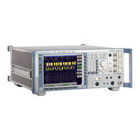
Rohde & Schwarz 1155.5001.26 Service Manual (406 pages)
Signal Analyzer
Brand:
Rohde & Schwarz
| Category:
Measuring Instruments
| Size: 8 MB
Table of Contents
Contents - Chapter 1 "Performance Test"
28
Table of Contents
28
Performance Test
30
Test Instructions
30
Measuring Equipment and Accessories
34
Performance Test R&S FSQ
35
Checking the Reference Frequency Accuracy
35
Checking Immunity to Interference
36
St if Image Frequency Rejection
37
Nd if Image Frequency Rejection
37
Rd if Image Frequency Rejection
37
St if Rejection
38
Nd if Rejection
38
Checking Nonlinearities
39
Third-Order Intercept Point
39
Second-Order Harmonic Distortion
40
Checking if Filters
41
Checking the Bandwidth Switching Level Accuracy
41
Checking Bandwidth
42
Checking the Shape Factor
42
Checking Noise Display
43
Checking the Level Accuracy and the Frequency Response
44
Frequency Response > 3.6 Ghz
46
Checking the Display Linearity
50
Checking the Display Linearity (Alternative Measurement)
52
Checking the RF Attenuator
57
Checking the RF Attenuator Accuracy (Alternative Measurement)
59
Checking the Reference Level Switching (IF-Gain)
61
Checking the Reference Level Switching Accuracy (Alternative Measurement)
63
Checking the Phase Noise for Instruments with Serial Numbers Smaller than 200000
65
Testing the Phase Noise at 639 Mhz or 640 Mhz for Instruments with Serial Number Larger than 200000
67
Alternative Phase-Noise Testing at 800 Mhz for Instruments with a Serial Number Larger than 200000
69
Checking the Return Loss at the RF Input
72
Checking the Frequency Response of the IQ Compensation Filter
73
Checking the Output Level
74
Test Procedure Option Tracking Generator B9 with Option Attenuator B12
74
Checking the Frequency Response
75
Checking the Dynamic Range
76
Checking Modulation
77
Checking the I/Q Modulator
77
Checking the Amplitude Modulation
78
Checking the Frequency Modulation
79
Performance Test Option Preamplifier FSU-B24
81
Checking Noise Display
81
Checking the Level Accuracy and the Frequency Response
82
Absolute Level Accuracy at 128 Mhz
83
Frequency Response < 3.6 Ghz
84
Performance Test Option Electronic Attenuator B25
89
Checking Noise Display with Preamplifier (B25)
89
Checking the Level Accuracy and the Frequency Response with Preamplifier
90
Frequency Response > 3.6 Ghz
97
Checking Nonlinearities with Electronic Attenuator
100
Third-Order Intercept
100
Checking the RF Attenuator (with Option B25)
101
Checking the RF Attenuator Accuracy with Option B25 (Alternative Measurement)
102
Checking the Electronic Attenuator Accuracy
104
Checking the Electronic Attenuator Accuracy with Option B25 (Alternative Measurement)
105
Checking LO-Level
107
Performance Test Option External Mixing B21
107
Checking the Input lo out / if in (2-Port-Mixers)
108
Checking the Input if in (3-Port-Mixers)
108
Checking the Bias Supply
109
Performance Test Option - B23
110
Checking Noise Display with Preamplifier (B23)
110
Checking the Level Accuracy and the Frequency Response with Preamplifier (B23)
111
Test Procedure for Option IQ Baseband Input FSQ-B71
114
Testing the Level Error (50 )
118
Checking the Level Error (1 K / 1M )
123
Dynamic Range (1 K / 1 M )
125
Test Procedure for Option I/Q Bandwidth Extension R&SFSQ-B72
127
Test Procedure for Option Digital Baseband Interface R&SFSQ-B17
145
Performance Test Report R&S FSQ
146
Performance Test Report Option R&S FSU-B9
168
Performance Test Report Option R&S FSU-B24
168
Performance Test Report Option B25
175
Performance Test Report Option FSU-B21
181
Performance Test Report Option B23
182
Performance Test Report Option R&S FSQ-B71
184
Performance Test Report Option R&S FSQ-B72
198
Performance Test Report Option R&S FSQ-B17
210
Contents - Chapter 2 "Adjustment"
212
Adjustment
214
Service Menu
214
Adjustment Functions
215
Entering the Password
215
Manual Adjustment
216
Measuring Equipment and Accessories
216
Test Instructions
216
Adjusting the Level Measurement Accuracy
217
Adjusting the Frequency Accuracy
219
Adjustment of Module Data
221
Frequency Response Correction
221
Contents - Chapter 3 "Repair"
222
Block Diagram
224
Fig. 3-1 Block Diagram of Instrument
224
Instrument Design and Function Description
224
Repair
224
Description of Block Diagram
225
Fig. 3-2 Input Attenuator
225
Fig. 3-3 Conversion of the RF to the Third if from 20 Hz to 3.6 Ghz
226
Fig. 3-4 Conversion of the RF to the if from 3.6 Ghz
227
Fig. 3-5 if Filter
228
Fig. 3-6 Processing of Measured Data
229
Fig. 3-7 Synchronization of 1St Local Oscillator
230
Fig. 3-8 Sweep Synthesizer
232
Module Replacement
235
Performing a Cold Start
236
Fig. 3-9 Removing the Front Module Controller
239
Replacing Front Module Controller A90
239
Fig. 3-10 Position of Connectors on Front Module Controller
240
Replacing Lithium Battery on Front Module Controller
241
Fig. 3-11 Position of Lithium Battery on Front Module Controller
242
Replacing Hard Disk A60
244
Replacing LCD and DC/AC Converter in Front Module
246
Fig. 3-12 Position of Connectors on Front Module Controller
247
Replacing Keyboard Membrane or Mat on Front Module
248
Fig. 3-13 Position of Connectors on Front Module Controller
249
Replacing Front Cover on Front Module
250
Replacing Floppy Disk Drive A30
251
Replacing Power Supply A20
252
Replacing Fan E1
253
Replacing RF Input Connector (Cable W1) R&S FSQ3/8
254
Replacing RF INPUT Connector (Testport Adapter) R&S FSQ26
255
Replacing RF-INPUT (Testport Adapter) R&S FSQ26
256
Replacing Motherboard A10
257
Replacing RF Attenuator A40
259
Replacing Probe Board Module A80 and Vol./Phone Board A191
261
Fig. 3-14 Pin Assignments of PROBE POWER Connector
262
Replacing USB2.0 Board A310
263
Replacing RF Frontend A100
265
Replacing Synthesizer A110
266
Replacing Detector A140
268
Replacing if Filter A130
269
Replacing 8 Ghz Converter Unit A160; FSQ8
270
Replacing Diplexer A162; FSQ8
272
Replacing 8 Ghz YIG Unit A161; R&S FSQ8
274
Replacing Relay on the MW Converter Unit; FSQ8
276
Replacing 26.5 Ghz MW Converter Unit A160; FSQ26/40
278
Replacing Diplexer A161; FSQ26/40
280
Replacing 26.5 Ghz YIG Unit 162; FSQ 26/40
282
Replacing Extender 26,5 Ghz A163; FSQ 26/40
284
Replacing Relay on the MW Converter Unit; FSQ26/40
286
Replacing Tracking Generator A170 (Option: B9)
288
Replacing Generator Attenuator A171 (Option: B12)
289
Replacing OCXO A200 (Option: B4)
290
Replacing Combo Drive A381 (Option: B18)
291
Replacing External Generator Control A210 (Option: B10)
292
Replacing Baseband Input 1 A270 (Option: B71)
294
Replacing Baseband Input 2 A260 (Option: B71)
295
Replacing I/Q Bandwidth Extension A280 (Option B72)
296
Replacing External Mixer Board A180 (Option B21)
298
Replacing Diplexer Board with Preamplifier A161; (Option B23)
299
Replacing Electronic Attenuator A50 (Option B25)
301
Replacing I/Q Memory Extension (Option B100)
302
Replacing Memory Modules (Option B102)
304
Replacing Preamplifier A50 (Option B24)
305
Replacing IQ DATA IN/OUT A290 (Option B17)
306
Measuring Equipment and Accessories
308
Troubleshooting Switch-On Problems
309
Troubleshooting Problems with Booting
310
Troubleshooting - Loading Module Eeproms
316
Troubleshooting Via Selftest
318
Troubleshooting RF Converter 1
335
Troubleshooting
336
Troubleshooting MW Converters
336
Troubleshooting - Wideband Detector Unit
339
Fig. 3-15 Video Path Differential Linearity Test, Error-Free Unit
340
Fig. 3-16 Video Path Differential Linearity Test, Faulty Unit (Blocked Bit)
340
Fig. 3-17 FFT Test, Noise Floor, Error-Free Unit
341
Fig. 3-18 Full-Scale Test, Error-Free Unit
342
Fig. 3-19 Phase Noise Test, Error-Free Unit
344
Fig. 3-20 Phase Noise Test, Faulty Unit (High Phase Noise)
344
Contents - Chapter 5 "Documents"
352
Documents
354
Shipping of a Module
354
Shipping of Instrument
354
Shipping of Instrument and Ordering of Spare Parts
354
Ordering Spare Parts
355
Refurbished Modules
355
Taking Back Defective Replaced Modules
355
Available Power Cables
356
Spare Parts
356
Mechanical Drawings
358
Spare Part List
358
Advertisement
Advertisement
Related Products
Rohde & Schwarz 1155.5001.03
Rohde & Schwarz 1155.5001.31
Rohde & Schwarz 1155.5001.08
Rohde & Schwarz 1155.5001.40
Rohde & Schwarz 1150.3998.12
Rohde & Schwarz 1145.5850.13
Rohde & Schwarz 1164.4391.07
Rohde & Schwarz 1119.6001.27
Rohde & Schwarz 1145.5850.06
Rohde & Schwarz 1145.1110.08/24
Rohde & Schwarz Categories
Measuring Instruments
Test Equipment
Portable Generator
Power Supply
Accessories
More Rohde & Schwarz Manuals
Login
Sign In
OR
Sign in with Facebook
Sign in with Google
Upload manual
Upload from disk
Upload from URL