Sign In
Upload
Manuals
Brands
Rockwell Automation Manuals
Controller
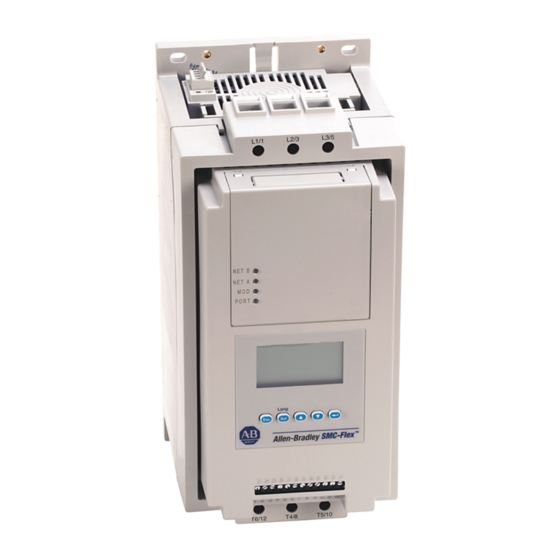
Allen-Bradley SMC-Flex 150
Rockwell Automation Allen-Bradley SMC-Flex 150 Manuals
Manuals and User Guides for Rockwell Automation Allen-Bradley SMC-Flex 150. We have
1
Rockwell Automation Allen-Bradley SMC-Flex 150 manual available for free PDF download: User Manual
Rockwell Automation Allen-Bradley SMC-Flex 150 User Manual (140 pages)
Brand:
Rockwell Automation
| Category:
Controller
| Size: 3 MB
Table of Contents
Table of Contents
5
Other Related Documents
13
Product Overview
13
Description
13
Operation
14
Modes of Operation (Standard)
14
Soft Start
14
Selectable Kickstart
15
Current Limit Start
15
Dual Ramp Start
16
Full Voltage Start
16
Preset Slow Speed
17
Linear Speed Acceleration
18
Soft Stop
19
Control Options
20
Modes of Operation (Pump Control)
20
Pump Control Option
20
Modes of Operation (Braking Control)
21
SMB Smart Motor Braking Option
21
Accu-Stop Option
22
Slow Speed with Braking Option
22
Protection and Diagnostics
23
Overload
23
Underload
23
Undervoltage
25
Overvoltage
25
Unbalance
25
Stall Protection and Jam Detection
26
Ground Fault
27
Thermistor/Ptc Protection
28
Excessive Starts/Hour
29
Overtemperature
30
Open Gate
30
Line Faults
30
Metering
31
Communication
31
Programming
32
Status Indication
32
Receiving
33
Unpacking
33
Inspecting
33
Storing
33
General Precautions
34
Heat Dissipation
34
Enclosures
34
Mounting
36
Dimensions
36
Power Factor Correction Capacitors
40
Protective Modules
41
Motor Overload Protection
41
Two-Speed Motors
41
Multi-Motor Protection
41
Electromagnetic Compatibility (EMC)
42
Enclosure
42
Wiring
42
Terminal Locations
43
Wiring
43
Power Structure
44
Power Wiring
45
Control Power
47
Control Voltage
47
Control Wiring
48
Fan Power
48
Fan Terminations
48
Control Terminal Designations
49
Standard Controller
50
Figure 3.10 Typical Wiring Diagram for Dual Ramp Applications
53
Figure 3.11 Typical Wiring Diagram for Start-Stop Control Via DPI
54
Figure 3.12 Typical Wiring Diagram for Retrofit Applications
55
Figure 3.13 Typical Wiring Diagram for Isolation Applications
56
Figure 3.14 Typical Wiring Diagram for Shunt Trip
57
Figure 3.15 Typical Wiring Diagram for Single-Speed Reversing Applications
58
Figure 3.16 Typical Wiring Diagram for Two-Speed Applications
59
Figure 3.17 Typical Wiring Diagram for SMC-Off-Bypass
60
Figure 3.18 Typical Wiring Diagram for Hand-Off-Auto (DPI)
61
Soft Stop, Pump Control, and SMB Smart Motor Braking
63
Figure 3.21 Typical Retrofit Wiring Diagram
64
Figure 3.22 Typical Wiring Diagram for Applications Requiring an Isolation Contactor
65
Figure 3.23 Typical Wiring Diagram for Hand-Off-Auto (DPI) Control (Soft Stop, Braking, and Pump Control Only)
66
Preset Slow Speed
67
Figure 3.24 Typical Wiring Diagram for the Preset Slow
67
Figure 3.25 Typical Slow Speed Wiring Diagram for Hand-Off-Auto (DPI) Control
68
Slow Speed with Braking
69
Figure 3.26 Typical Wiring Diagram for the Slow Speed with
69
Sequence of Operation
70
Figure 3.27 Soft Stop Sequence of Operation
70
Figure 3.28 Preset Slow Speed Sequence of Operation
71
Figure 3.29 Pump Control Sequence of Operation
72
Figure 3.30 SMB Smart Motor Braking Sequence of
73
Figure 3.31 Accu-Stop Sequence of Operation
74
Figure 3.32 Slow Speed with Braking Sequence of Operation
75
Overview
77
Programming
77
Keypad Description
77
Programming Menu
77
Figure 4.1 Menu Structure Hierarchy
78
Figure 4.2 Parameter Menu Structure
79
Password
81
Parameter Management
82
Random Access Memory (RAM)
82
Read-Only Memory (ROM)
82
Electrically Erasable Programmable Read-Only Memory (EEPROM)
82
Figure 4.3 Memory Block Diagram
82
Using Parameter Management with DPI HIM
83
Parameter Modification
84
Soft Start
85
Current Limit Start
85
Dual Ramp Start
86
Full Voltage Start
87
Linear Speed
87
Programming Parameters
88
Basic Set up
91
Motor Protection
92
Example Settings
93
Undervoltage
93
Overvoltage
93
Jam
93
Underload
93
Overview
94
Motor Information
94
Motor Data Entry
94
Viewing Metering Data
95
Overview
95
Optional HIM Operation
97
Human Interface Module
97
Overview
99
Communication Ports
99
Human Interface Module
99
Keypad Description
100
Connecting the Human Interface Module to the Controller
102
HIM Control Enable
102
Control Enable
104
Loss of Communication and Network Faults
104
SMC-Flex Specific Information
104
Default Input/Output Configuration
105
Variable Input/Output Configuration
105
SMC - Flex Bit Identification
106
Reference/Feedback
107
Parameter Information
107
Scale Factors for PLC Communication
107
Read Example
107
Write Example
107
Display Text Unit Equivalents
107
Configuring Datalinks
107
Rules for Using Datalinks
108
Updating Firmware
108
Overview
109
Protection Programming
109
Fault Display
109
Clear Fault
110
Fault Buffer
110
Fault Codes
111
Fault and Alarm Auxiliary Contact
111
Fault Definitions
112
Introduction
113
Troubleshooting
113
Power Module Check
118
Functional Design Specifications
119
Wiring Diagram
120
Electrical Ratings
120
Environmental
122
Mechanical
123
Other
123
Approximate Dimensions and Shipping Weights
124
Open Type Controllers
124
Enclosed Type Line-Connected Controllers
124
Enclosed Type Delta-Connected Controllers
125
Communications
132
Control
133
Control
134
Braking
134
Operation
136
Advertisement
Advertisement
Related Products
Rockwell Automation Allen-Bradley 1769 Compact GuardLogix
Rockwell Automation Allen-Bradley 5069 Compact GuardLogix
Rockwell Automation Allen-Bradley 1756 GuardLogix
Rockwell Automation Allen-Bradley MicroLogix
Rockwell Automation Allen-Bradley GuardLogix
Rockwell Automation Allen-Bradley MicroLogix 1400 Series
Rockwell Automation Allen-Bradley PowerFlex 70
Rockwell Automation Allen-Bradley PowerFlex Series
Rockwell Automation Allen-Bradley PowerFlex 525
Rockwell Automation Allen-Bradley PowerFlex 4M
Rockwell Automation Categories
Controller
Control Unit
Power Supply
DC Drives
Industrial Equipment
More Rockwell Automation Manuals
Login
Sign In
OR
Sign in with Facebook
Sign in with Google
Upload manual
Upload from disk
Upload from URL