Sign In
Upload
Manuals
Brands
Rockwell Automation Manuals
Servo Drives
2198-D032-ERS3
Rockwell Automation 2198-D032-ERS3 Manuals
Manuals and User Guides for Rockwell Automation 2198-D032-ERS3. We have
1
Rockwell Automation 2198-D032-ERS3 manual available for free PDF download: User Manual
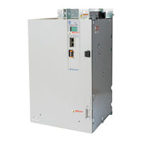
Rockwell Automation 2198-D032-ERS3 User Manual (456 pages)
Brand:
Rockwell Automation
| Category:
Servo Drives
| Size: 68 MB
Table of Contents
Table of Contents
3
Preface
11
Download Firmware, AOP, EDS, and Other Files
11
Summary of Changes
11
Access Fault Codes
11
Conventions Used in this Manual
12
CIP Security
12
Additional Resources
13
Start
15
Kinetix 5700 Servo Drives Series Change
16
About the Kinetix 5700 Servo Drive System
16
DC-Bus Power Supply Input Power Configurations
19
Typical DC-Bus Power Supply Configuration Example
19
Multiple DC-Bus Power Supply Configuration Example
20
Extended DC-Bus Configuration Example
21
Itrak Power Supply Configuration Example
22
Regenerative Bus Supply Input Power Configurations
23
Typical Regenerative Bus Configuration Examples
23
Extended Regenerative Bus Configuration Example
26
8720MC-RPS Power Supply Input Power Configuration
27
Motor and Auxiliary Feedback Configurations
28
Typical Communication Configurations
29
Linear Topology
29
Ring Topology
30
Star Topology
31
Functional Safety Configurations
32
Hardwired Configuration
32
Integrated Safety Configurations
33
Safe Stop and Safe Monitor Configurations
35
Catalog Number Explanation
36
Agency Compliance
37
System Design Guidelines
39
System Mounting Requirements
39
DC-Bus Voltage Regulation
40
AC Line Filter Selection
42
AC Line Impedance Considerations
43
Circuit Breaker/Fuse Selection
46
24V Control Power Evaluation
47
Contactor Selection
48
Passive Shunt Considerations
49
Active Shunt Considerations
50
Enclosure Selection
51
Minimum Clearance Requirements
53
Multi-Axis Shared DC-Bus Configurations
55
Accessory Module Selection
56
DC-Bus Power Supply Systems
56
Regenerative Bus Supply Systems
58
8720MC-RPS or Other Regenerative Power Supply
61
Accessory Module Flowcharts
62
Electrical Noise Reduction
64
HF Bond for Modules
64
HF Bond for Multiple Subpanels
66
Establish Noise Zones
67
Cable Categories for Kinetix 5700 Systems
69
Noise Reduction Guidelines for Drive System Accessories
70
Mount the Kinetix 5700 Drive System
78
Determine Mounting Order
78
Mount Accessory Modules
81
Zero-Stack Tab and Cutout
82
Install Shared-Bus Connection Systems
82
DC-Bus Connection System
82
24V Input Power Connection System
83
Drill-Hole Patterns
85
Drill-Hole Pattern Calculations
86
Drill-Hole Patterns by Using the System Mounting Toolkit
88
Mount Your Kinetix 5700 Drive Modules
88
Connector Data and Feature Descriptions
91
Safe Torque-Off Connector Pinout
99
Input Power Connector Pinouts
99
DC Bus and Shunt Resistor Connector Pinouts
100
Digital Inputs Connector Pinouts
101
Ethernet Communication Connector Pinout
102
Motor Power, Brake, and Feedback Connector Pinouts
102
Motor Feedback Connector Pinouts
103
Universal Feedback Connector Pinouts
104
Accessory Module Pinouts
104
Understand Control Signal Specifications
105
Digital Inputs
105
Ethernet Communication Specifications
106
Contactor Enable Relay
107
Converter OK Relay
108
Motor Brake Circuit
108
Control Power
110
Feedback Specifications
111
Encoder Feedback Supported on the DSL Feedback Connector
111
Encoder Feedback Supported on the UFB Feedback Connector
111
Auxiliary Feedback Specifications
114
Encoder Phasing Definitions
115
Absolute Position Feature
117
Functional Safety Features
118
Hardwired STO Mode
118
Integrated Mode
118
Basic Wiring Requirements
120
Routing the Power and Signal Cables
120
Input Power Configurations for Kinetix 5700 Power Supplies
121
DC-Bus Power Supply
121
Regenerative Bus Supply
124
Ground Screw/Jumper Settings
127
Kinetix 5700 Drive System Power Supply
127
Kinetix 5700 Inverters
128
Kinetix 5700 Itrak Power Supply
129
Remove/Install the Ground Screw/Jumper
130
Ground the Drive System
131
Ground the System Subpanel
131
Ground Multiple Subpanels
132
Wiring Requirements
133
Wiring Guidelines
137
Wire the Power Connectors
137
Wire the 24V Control Power Input Connector
137
Wire the Input Power Connector
139
Wire the Contactor Enable Connector
140
Wire the Digital Input Connectors
141
2198-XXXX-ERS3 (Series A) Connector Plugs
141
2198-XXXX-ERS4 and 2198-XXXX-ERS3 (Series B) Connector Plugs
142
Wire the Safe Torque-Off Connector
142
Wire the Digital Inputs Connector
143
Wire Motor Power and Brake Connectors
144
Maximum Cable Lengths
147
Connect Single Cables
151
Motor Feedback Connections
152
Apply the Single Motor Cable Shield Clamp
153
Connect Power/Brake and Feedback Cables
155
Motor Power and Brake Cables
155
Motor Power/Brake Cable Series Change
156
Dual-Axis Inverter Power/Brake Cable Installation
156
Single-Axis Inverter Power/Brake Cable Installation
159
Motor Feedback Connections
163
Customer-Supplied Motor Power Cables
169
Accessory Module Connections
171
External Passive-Shunt Connections
172
External Active-Shunt Connections
173
DC-Bus Power Supply Active Shunt Connections
173
Regenerative Bus Supply Active Shunt Connections
173
Wire the External DC-Bus Connections
174
Kinetix VPC Motors and the Extended Speed Feature
175
Considerations for Powerohm Shunt Installation
175
Ethernet Cable Connections
176
Understand the Kinetix 5700 Display
178
Menu Screens
179
Setup Screens
182
Startup Sequence
187
Configure the Drive
188
Set the Network Parameters
188
Studio 5000 Logix Designer
188
Version History
188
Install the Kinetix 5700 Add-On Profile
189
Configure the Logix 5000 Controller
190
Configure the Kinetix 5700 Drive Modules
193
Configure the DC-Bus Power Supply
193
Configure the Regenerative Bus Supply
197
Configure the Itrak Power Supply
200
Configure the Inverter Drives
204
Continue Inverter Configuration
211
Configure the Motion Group
215
Configure Regenerative Bus Supply Axis Properties
216
Configure Vertical Load Control Axis Properties
221
Configure Feedback-Only
222
Axis Properties
222
Configure Induction-Motor Frequency-Control Axis Properties
223
General and Motor Categories
223
Basic Volts/Hertz Method
224
Sensorless Vector Method
226
Fan/Pump Volts/Hertz Method
228
Configure IPM Motor Closed-Loop Control Axis Properties
229
Configure SPM Motor Closed-Loop Control Axis Properties
233
Configure Induction-Motor Closed-Loop Control Axis Properties
238
Configure Feedback Properties
244
Configure Module Properties
244
Configure Axis Properties
246
Download the Program
249
Apply Power to the Kinetix 5700 Drive System
249
Understand Bus-Sharing Group Configuration
251
Bus-Sharing Group Example
252
Configure Bus-Sharing Groups
253
Test and Tune the Axes
254
Test the Axes
255
Tune the Axes
256
Safety Precautions
257
Interpret Status Indicators
258
Display Interface
258
Fault Code Overview
258
Fault Codes
259
SAFE FLT Fault Codes
259
Kinetix 5700 Status Indicators
260
Kinetix 5700 Accessory Module Status Indicators
261
Axis Troubleshooting
262
Regenerative Bus Supply Troubleshooting
263
Logix 5000 Controller and Drive Module Behavior
264
DC-Bus Power Supply Behavior
265
Regenerative Bus Supply Behavior
267
Itrak Power Supply Behavior
268
Inverter Behavior
270
Remove and Replace Drive Modules
275
Before You Begin
275
Remove Power and All Connections
276
Remove the Drive Module
278
Replace the Drive Module
279
Start and Configure the Drive Module
280
Replace 2198-XXXX-ERS3 (Series A) Drives with Series B Drives
280
Kinetix 5700 Safe Torque-Off Function
283
Overview
283
Certification
284
Average Frequency of a Dangerous Failure
285
Safe Torque-Off Feature
285
Out of Box State
286
Safe Torque-Off Status
289
Explicit Messages
290
Hardwired Safe Torque-Off
291
Compatible Controllers
291
Description of Operation
292
Troubleshoot the Safe Torque-Off Function
294
Safe Torque-Off Connector Data
296
Wire the Safe Torque-Off Circuit
297
Safe Torque-Off Wiring Requirements
299
Safe Torque-Off Feature Bypass
300
Cascade the Safe Torque-Off Signal
300
Hardwired Safe Torque-Off Electrical Specifications
302
Integrated Safe Torque-Off
302
Compatible Safety Controllers
302
Safety Application Requirements
303
Description of Operation
304
Safe Torque-Off Assembly Tags
304
STO Fault Reset
307
Understand Integrated Safety Drive Replacement
308
Replace an Integrated Safety Drive in a Guardlogix System
309
Motion Direct Commands in Motion Control Systems
310
Integrated Safe Torque-Off Specifications
316
Interconnect Diagram Notes
319
Power Wiring Examples
321
Capacitor Module Status Wiring Example
335
DC-Bus Conditioner Module Status Wiring Example
335
Contactor Wiring Examples
336
Passive Shunt Wiring Examples
337
Active Shunt Wiring Examples
338
Kinetix 5700 Servo Drive and Rotary Motor Wiring Examples
340
Kinetix 5700 Servo Drive and Linear Actuator Wiring Examples
347
System Block Diagrams
353
Before You Begin
361
Inhibit the Module
363
Upgrade Your Firmware
363
Use Controlflash Plus Software to Upgrade Your Drive Firmware
364
Use Controlflash Software to Upgrade Your Drive Firmware
367
Verify the Firmware Upgrade
372
Shared DC-Bus Configurations
373
Shared DC-Bus Definitions
373
General Sizing Guidelines
375
System Sizing Guidelines
375
Select Drive/Motor Combinations
376
Select the Power Supply and Define the DC-Bus Groups
376
Calculate System and External-Bus Capacitance
376
Calculate the Total Motor Power Cable Length
377
Calculate 24V DC Control Power Current Demand
378
24V DC Voltage Drop Calculation Example
379
System Sizing Example
381
System Sizing Application Example
382
DC-Bus Power Supply Configurations
384
Regenerative Bus Supply Configurations
387
Third-Party Motor Configurations
388
DC-Bus Power Supply Configurations
388
Regenerative Bus Supply Configurations
389
Regenerative Bus Supply Sequence Operation
391
Initialization
392
Precharge
393
Start Inhibited
393
Stopped
394
Starting
394
Running
394
Converter Startup Method - Automatic
395
Sequence Operation of Discharging
396
Motor Control Feature Support
398
Basic Volts/Hertz
399
Basic Volts/Hertz for Fan/Pump Applications
400
Sensorless Vector
401
Current Limiting for Frequency Control
402
The Effects of Current Limiting
402
Enable the Current Limiting Feature
404
Set the Currentvectorlimit Attribute Value
404
Stability Control for Frequency Control
405
Enable the Stability Control Feature
406
Skip Speeds
407
Multiple Skip Speeds
408
Flux up
409
Flux up Attributes
410
Configure the Flux up Attributes
411
Current Regulator Loop Settings
412
Motor Category
412
Motor Tests and Autotune Procedure
414
Motor Analyzer Category Troubleshooting
415
Selection of Motor Thermal Models
418
Generic Motors
418
Thermally Characterized Motors
419
Speed Limited Adjustable Torque (SLAT)
420
Motion Polarity Setting
420
SLAT Min Speed/Torque
421
SLAT Max Speed/Torque
422
SLAT Attributes
422
Configure the Axis for SLAT
423
Motion Drive Start (MDS) Instruction
426
Motor Overload Retention
431
Phase Loss Detection
432
Phase-Loss Detection Attributes
432
Phase-Loss Detection Configuration
433
Phase Loss Detection Current Example
434
Velocity Droop
434
Closed Loop Control
434
Frequency Control
435
Velocity Droop Configuration
435
Commutation Self-Sensing Startup
436
Commutation Test
437
Adaptive Tuning
438
Virtual Torque Sensor
438
Field Weakening Mode
439
Extended Speed Feature
439
Configure Extended Speed Operation
440
History of Changes
441
Index
445
Advertisement
Advertisement
Related Products
Rockwell Automation 2198-D006-ERS3
Rockwell Automation 2198-D012-ERS3
Rockwell Automation 2198-D020-ERS3
Rockwell Automation 2198-D057-ERS3
Rockwell Automation 2198-D006-ERS4
Rockwell Automation 2198-D012-ERS4
Rockwell Automation 2198-D020-ERS4
Rockwell Automation 2198-D032-ERS4
Rockwell Automation 2198-D057-ERS4
Rockwell Automation 2198-DCBUSCOND-RP312
Rockwell Automation Categories
Controller
Control Unit
Power Supply
DC Drives
Industrial Equipment
More Rockwell Automation Manuals
Login
Sign In
OR
Sign in with Facebook
Sign in with Google
Upload manual
Upload from disk
Upload from URL