Sign In
Upload
Manuals
Brands
Robur Manuals
Chiller
GA Line ACF Series
Robur GA Line ACF Series Manuals
Manuals and User Guides for Robur GA Line ACF Series. We have
1
Robur GA Line ACF Series manual available for free PDF download: Installation, Use And Maintenance Manual
Robur GA Line ACF Series Installation, Use And Maintenance Manual (97 pages)
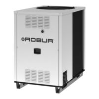
GA Line ACF Series Gas fired absorption chiller for cooling medium-large areas
Brand:
Robur
| Category:
Chiller
| Size: 7 MB
Table of Contents
Icon Definitions
3
Table of Contents
5
Safety Warnings
7
Section 1 General Information and Technical Specifications
7
If You Smell Gas
8
General Information
9
First Start-Up Procedure
10
Constructive Characteristics
12
Operation of the Acf60-00
12
Safety and Control Devices
12
Technical Specifications
15
Cooling Capacity Correction Factors
16
Heating Capacity of the Heat Recovery Unit
26
Operational Mode: Air Conditioning + Heat Recovery
26
PRESSURE DROP with Glycolated Water at 40%, Nominal Conditions
27
PED Characteristics
29
ACF Dimensions and Service Panels
30
Before Turning on the ACF, Check
33
Commissioning (and Shutdown) of the ACF
33
Errors During the Start-Up Phase of the ACF
33
Section 2 End User
33
On-Board Electronics
34
Menu Description
35
Display and Knob (Encoder)
36
To Navigate Using the Knob
38
Access to the Circuit Board Menu’s
38
Setting of Operating Parameters
39
Resetting
39
Warning and Error Codes
41
Displayed Codes
41
Prolonged Inactivity
42
To Shut down the ACF for a Long Period of Inactivity
42
ACF Start-Up after an Extended Period of Inactivity
42
Section 3 Plumbing Installer
43
General Installation Principles
43
Lifting the ACF
44
Positioning of the Acf60-00
44
Minimum Distances to Respect for the Correct Functioning of the ACF
45
Water Connections
46
Ground Installation
46
Roof or Terrace Installation
46
Supports and Levelling
46
Accumulation Tank
49
Connection of more than One Chiller
50
Gas Supply System
51
Filling of the Water Circuit
52
Use of Monoethylene Glycol (Antifreeze)
52
Activate the Automatic Air Release Valves on the Plant
52
Setting of the Water Parameters
54
Operation with Control Switch
57
Section 4 Electrical Installer
57
ACF Hook-Up
58
To Connect the ACF to the Electrical Power Supply
58
Appliance Pump Control
59
Controlling the Pump by Means of the ACF Circuit Board
59
Heat Recovery Circulator Pump Control (Only for HR Model)
59
Pump and Electrical Wiring Diagrams
60
Pump Controlled by the ACF with Control Relay, Power Draw
60
Heat Recovery Circulator Pump Connection
61
Pump Connection for N.2 ACF - HR
62
Independent Pump Connection for Several ACF - HR
63
Use of a Direct Digital Controller (DDC)
64
CAN BUS Cable
65
Connection of the CAN BUS Cable to the ACF
66
Connection of the CAN BUS Cable to the DDC
69
Connection of the DDC to the Electrical Power Supply
71
Connection of the Pump
72
Diagram of One ACF Connected to a Direct Digital Controller (DDC)
73
Diagram of Two Acf60'S Connected to a Direct Digital Controller (DDC)
74
Example of Pump/Appliance Electrical Connection with 230 Vac Pump
75
How to Reset the Flame Controller from Remote
76
Section 5 Initial Startup and Maintenance
77
Initial Startup and Adjusting
77
Gas Flow Adjustment
78
To Check the Static Gas Pressure of the Network
78
Gas Conversion
80
Gas Conversion Operations
82
Maintenance
83
To Clean the Coil
83
Addition of Water and Antifreeze to the Water Circuit
84
Section 6 Accessories
85
Warnings and Errors
87
Table of Operating Codes Generated by the Electronic Board
87
Appendix
87
Appendix
91
Declaration of Conformity
91
Advertisement
Advertisement
Related Products
Robur GA ACF
Robur GA ACF60-00
Robur GA ACF60-00 TK
Robur GA ACF60-00 HT
Robur GA ACF60-00 LB
Robur GA ACF60-00 HR
Robur Gitie 2.0 ACAY
Robur GA ACF HT
Robur GA ACF HR
Robur GA ACF TK
Robur Categories
Heat Pump
Gas Heater
Heater
Boiler
Chiller
More Robur Manuals
Login
Sign In
OR
Sign in with Facebook
Sign in with Google
Upload manual
Upload from disk
Upload from URL