Roberts Gorden Blackheat BH35ST Manuals
Manuals and User Guides for Roberts Gorden Blackheat BH35ST. We have 2 Roberts Gorden Blackheat BH35ST manuals available for free PDF download: Installation, Operation & Service Manual
Roberts Gorden Blackheat BH35ST Installation, Operation & Service Manual (84 pages)
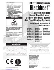
Vacuum Assisted Linear, Double Linear, U-Tube, and Multi-Burner Gas Fired Heating Systems
Brand: Roberts Gorden
|
Category: Heating System
|
Size: 13 MB
Table of Contents
Advertisement

Roberts Gorden Blackheat BH35ST Installation, Operation & Service Manual (84 pages)
Blackheat Vacuum Assisted Linear, Double Linear, U-Tube, and Multi-Burner Gas Fired Heating Systems
Brand: Roberts Gorden
|
Category: Gas Heater
|
Size: 14 MB
Table of Contents
Advertisement
Related Products
- Roberts Gorden Blackheat BH30UT
- Roberts Gorden Blackheat BH30EF
- Roberts Gorden Blackheat BH35UT
- Roberts Gorden Blackheat BH35EF
- Roberts Gorden Blackheat BH30ST
- Roberts Gorden Blackheat BH25UT
- Roberts Gorden Blackheat BH25EF
- Roberts Gorden Blackheat BH45UT
- Roberts Gorden Blackheat BH25ST
- Roberts Gorden Blackheat BH45ST