Sign In
Upload
Manuals
Brands
RINCO ULTRASONICS AG Manuals
Welding System
Standard 3000
RINCO ULTRASONICS AG Standard 3000 Manuals
Manuals and User Guides for RINCO ULTRASONICS AG Standard 3000. We have
1
RINCO ULTRASONICS AG Standard 3000 manual available for free PDF download: Operating Instructions Manual
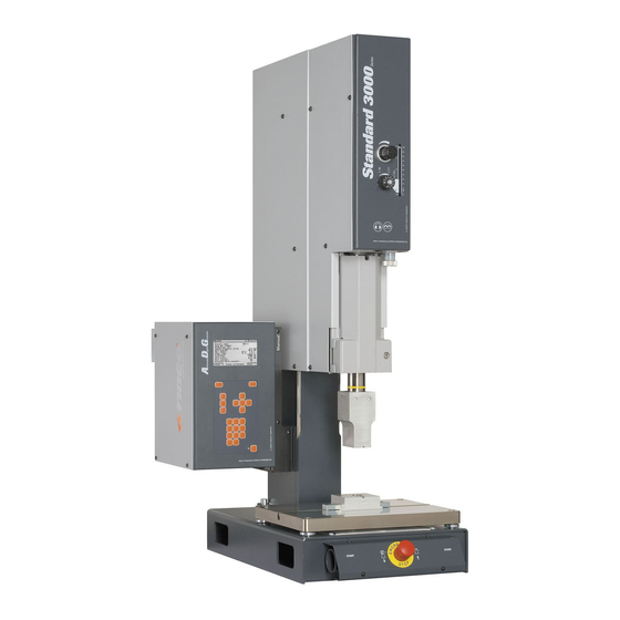
RINCO ULTRASONICS AG Standard 3000 Operating Instructions Manual (137 pages)
Brand:
RINCO ULTRASONICS AG
| Category:
Welding System
| Size: 2 MB
Table of Contents
Table of Contents
3
Fig. 6 Controls and Indicators Welding Press
1
Fig. 7 Controls and Indicators Welding Press
2
Table of Contents
3
Tab. 12 Setting up Parameterization PIN
4
Fig. 38 Jumpers
4
Tab. 33 Sound Enclosure Errors
5
1 General Information
7
Information on These Operating Instructions
7
Explanation of Symbols
8
Disclaimer
9
Warranty Terms
10
Customer Service and Product Monitoring
11
Fig. 1 Type Plates
11
2 Safety Requirements
12
Introduction
12
Responsibility of the Operator
12
Personnel Requirements
13
General Personnel Requirements
13
Qualifications
13
Unauthorised Persons
14
Personal Protective Equipment
15
Residual Risks
16
Hazards from Electric Energy
16
Mechanical Hazards
17
Hazards at the Operating Site
18
Pneumatic Hazards
18
Emergency Shutdown
19
What to Do in the Event of Dangers and Accidents
19
Preventative Measures
19
Measures in the Event of Accidents
19
Fig. 2 EMERGENCY STOP Button
19
Symbols/Pictograms
20
Intended Use
21
3 Machine Description
23
Overview/Assemblies
23
Complete System
23
Fig. 3 Complete System
23
Tab. 1 Press Design
23
Sound Enclosure (Optional)
24
Tab. 2 Sound Enclosure
24
Oscillator Unit
25
Fig. 5 Oscillator Unit
25
Tab. 3 Reducer Booster
26
Tab. 4 Booster Standard
26
Controls and Indicators
27
Welding Press
27
Tab. 5: Welding Press Part 1
27
Tab. 6: Welding Press Part 2
28
Fig. 8 Pressure Regulator DR
30
Fig. 9 Throttle VD Diagram
31
Fig. 10 Throttle VD Display
31
Generator/Aui Control Module
32
Fig. 11 Generator Overview
32
Tab. 7 Control Module AUI
32
Fig. 12 PIN Codes
33
Menu Tree
35
Fig. 13: Menu Tree 1/3
35
Fig. 14: Menu Tree 2/3
36
Fig. 4 Sound Enclosure
37
Fig. 15: Menu Tree 3/3
37
Connections
38
Electrical Connection
38
Fig. 16 Electrical Connections of Generator
38
Tab. 8 Generator Connections
38
Compressed Air Connection
39
Fig. 17 Compressed Air Connection
39
Marking Locations
40
Fig. 18 Type Plates
40
Fig. 19 Marking Locations
40
Welding Technology
41
Fig. 20 Welding Parameters - Contact Force and Amplitude
41
Fig. 21 Stop Conditions
41
Process
42
Fig. 22 Welding Cycle Sequences
42
Programming an Initial Application
43
Fig. 23 System Pressure DR and Throttle VD, Setting Knobs
43
Fig. 24 System Pressure DR and Throttle VD, Diagram
43
Welding Modes
44
Fig. 25 TIME MODE
44
Fig. 26 TRAVEL MODE Difference
44
Fig. 27 TRAVEL MODE Absolute
44
Fig. 28 ENERGY MODE
45
4 Transport, Packaging and Storage
46
Safety Warnings for Transport
46
Delivery (Packaging/Packages)
48
Transporting Packages by Forklift Truck or Lifting Cart
49
Transporting the Sound Enclosure by Forklift Truck or Lifting Cart
50
Transporting by Crane
51
Fig. 30 Lifting the Press
51
Fig. 31 Lifting the Sound Enclosure
52
Transport Inspection
53
Storage and Extended Downtimes
54
Pictograms on the Packages
55
5 Assembly and Initial Start-Up
56
Safety Instructions Regarding the Installation
56
Set-Up Location Requirements
58
Fig. 32 View of Workplace
59
Fig. 33 Sound Enclosure Dimensions
60
Fig. 34 Workplace Dimensions
60
Setting up the Machine
61
Fig. 35 Sound Enclosure
61
Connecting the Machine
62
Electrical Connections
62
Fig. 36 Generator (Connections)
63
Compressed Air Connection
64
Jumpers
64
Fig. 37 Pneumatic System
64
6 Operation
65
Safety
65
Hazards from Electric Energy
65
Hazards from Incorrect Operation
66
Hazards from Vapours and Particulate Emissions
66
Hazards from Noise Emission
67
Hazards from Materials
67
Mechanical Hazards
68
Example Application
69
ADG Generator
69
Fig. 39 ADG Generator Signals
69
Fig. 40 ADG Generator Process Steps
69
ADG Generator Error Signals
70
Fig. 41 ADG Generator Error Signals
70
Fig. 42 Process Sequence
70
ADG Generator and Sound Enclosure
71
Fig. 29 Sound Enclosure
71
Fig. 43 Signals of ADG Generators with Sound Enclosure
71
Fig. 44 Process Steps of ADG Generator with Sound Enclosure
71
ADG Generator with Special Actuators (Automatic Start Mode)
72
Fig. 45 ADG with Special Actuators
72
Fig. 46 Process Sequence
72
Switch Data Set Function
73
Tab. 9 "Switch Data Set Function" Dec
73
Tab. 10 "Switch Data Set Function" bin
73
Fig. 47 Start Signals
75
Process Programming
76
Setting up Parameterization PIN
76
Advanced System Operation
77
Tab. 13: System Functions (PIN) Option 1
78
Tab. 14 System Functions (PIN) Option
79
Tab. 15 System Functions (PIN) Sonotrode
79
Tab. 16 System Functions (PIN) Generator Parameters
80
Tab. 17 System Functions (PIN) Settings
81
Tab. 18 System Functions (PIN) Country Settings
81
Tab. 19 System Functions (PIN) System Test
81
Tab. 20 Analysis (PIN)
82
Tab. 21 Reset Functions (PIN)
82
Data Analysis
83
Statistics
83
Data String
84
Fig. 48 Data String
84
Logging Parameter Data Set Via RS232
86
Setting up
87
Installing the Oscillator System
87
Fig. 49 Oscillator System
87
Replacing the Booster
88
Setting up the Tool
88
Fig. 50 Replacing the Booster
88
Fig. 51 Tool
88
Fig. 52 Setting the Fine Adjustment Screw
88
Fig. 53 Releasing the Clamping Lever
88
Tab. 22 Workpiece Set-Up
88
Fig. 54 EMERGENCY STOP Button
89
Fig. 55 Manual Check Valve
89
Fig. 56 Lowering with Two-Hand Release
89
Fig. 57 Centring the Anvil
89
Fig. 58 Releasing the Clamping Lever
90
Fig. 59 Tightening the Clamping Lever
90
Fig. 60 Tightening the Clamps
90
Fig. 61 Lifting with Two-Hand Release
90
Aligning the Fixing Plate
91
Fig. 62 Aligning the Fixing Plate
91
Steps Prior to Use
92
Starting the Machine
92
Switching off
93
Fig. 63 Generator Control Console
93
Fig. 64 Manual Check Valve
93
7 Maintenance
94
Safety Instructions
94
Maintenance Schedule
95
Daily Maintenance Work on Work Finish
95
Tab. 23 Daily Maintenance Work on Work Finish
95
Semi-Annual Maintenance Work
96
Annual Maintenance Work
96
Tab. 24 Semi-Annual Maintenance Work
96
Tab. 25 Annual Maintenance Work
96
Maintenance Work
97
Cleaning the Machine and Surrounding Area
97
Fig. 65 Parts to be Cleaned
97
Fig. 66 Fixing Plate
97
Fig. 67 Oscillator System, Danger of Electric Shock
98
Fig. 68 Oscillator System Assembly
98
Servicing the Compressed Air Maintenance Unit
99
Measures after Completion of the Maintenance Work
99
8 Faults
100
Safety
100
What to Do in the Event a Fault Poses a Danger
101
Troubleshooting
101
General Errors
101
Generator Error LED1
101
Tab. 26 General Errors
101
Converter and Application Error LED2
102
Tab. 27 Generator Error LED1
102
Limit Error LED3
103
Tab. 28 Converter and Application Error LED2
103
Description of Error Range (Error Group)
104
Tab. 29 Limit Error LED3
104
Tab. 30 Description of Error Range (Error Group)
104
Error Tables
105
Generator Errors
105
Tab. 31 Generator Errors
106
Press Errors
107
Sound Enclosure Errors
107
Tab. 32 Press Errors
107
Limit Errors
109
Tab. 34 Limit Errors
109
Digital I/O Errors
110
Hardware Errors
110
Tab. 35 Digital I/O Errors
110
Serial RS232 Error
112
Tab. 36 Hardware Errors
112
Tab. 37 RS232 Errors
112
Canopen Errors
113
Limit Warnings
113
Tab. 38 Canopen Errors
113
Tab. 39 Limit Warnings
113
Parameter Warnings
114
Tab. 40 Parameter Warnings
114
Troubleshooting Measures after Completion of Work
115
9 Disassembly and Disposal
116
Safety
116
Personnel
116
Personal Protective Equipment
116
Safety Instructions
117
Measures before Disassembly
118
Disposal
118
10 Technical Data
119
General Information
119
Dimensions and Weights
119
Fig. 69 Press Dimensions
119
Tab. 41 Dimensions and Weights
119
Tab. 42 Generator Dimensions
119
Fig. 70 Sound Enclosure Dimensions
120
Tab. 43 Sound Enclosure Dimensions
120
Tab. 44 Weights
120
Connected Loads, Limit Values, Electrical
121
Connected Loads, Pneumatic
121
Tab. 45 Connected Loads, Limit Values, Electrical
121
Tab. 46 Connected Loads, Pneumatic
121
Press
122
Base
122
Tab. 47 Technical Data of Press
122
Tab. 48 Technical Data of Base
122
Generator/Control
123
Fuses
123
Fig. 71 Generator Front
123
Fig. 72 Installation Position of Generator Fuses
123
Fig. 73 Generator Fuses Dimensions
123
Tab. 49 Technical Data of Generator/Control
123
Tab. 50 Technical Data of Fuses
123
Analogue and Digital Inputs and Outputs
124
Tab. 51 Voltage Supply and Voltage Level
124
Tab. 52 Overview of Inputs and Outputs
124
Fig. 74 Internal Resistance Analogue Input
125
Fig. 75 Internal Resistance Analogue Output
125
Ultrasound
126
Emissions
126
Operating Conditions
126
Tab. 53 Technical Data of Ultrasound
126
Tab. 54 Emissions
126
Tab. 55 Operating Conditions
126
Pin Assignments
127
Tab. 56 Pin Assignment STO_2_1
127
Tab. 57 Pin Assignment STO_2_2
128
Press at STO_3
129
Tab. 58 Pin Assignment STO_3
129
Two-Hand Release at STO_5
130
Tab. 59 Pin Assignment STO_5
130
11 Replacement Parts
131
12 EC Declaration of Conformity for Machines
132
List of Figures
133
Advertisement
Advertisement
Related Products
RINCO ULTRASONICS AG HW35-3
RINCO ULTRASONICS AG RL35
RINCO ULTRASONICS AG Categories
Welding System
Portable Generator
More RINCO ULTRASONICS AG Manuals
Login
Sign In
OR
Sign in with Facebook
Sign in with Google
Upload manual
Upload from disk
Upload from URL