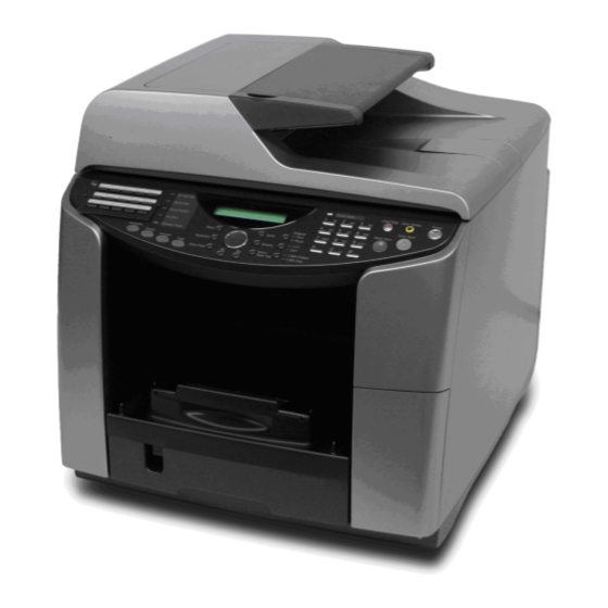
Sign In
Upload
Manuals
Brands
Ricoh Manuals
Printer
J012
Ricoh J012 Manuals
Manuals and User Guides for Ricoh J012. We have
1
Ricoh J012 manual available for free PDF download: Service Manual
Ricoh J012 Service Manual (448 pages)
Brand:
Ricoh
| Category:
Printer
| Size: 45.74 MB
Table of Contents
Service Manual
1
Table of Contents
13
Installation
23
Read this First
25
Safety Information
25
Safety Instructions
25
Conventions Used in this Manual
38
1 Installation
43
Preparation
45
Environment
45
Choosing a Location
46
Minimum Space Requirements
47
Power Source
47
Computer Hardware and Software
48
Using the Operation Panel
49
Summary of Important Operation Panel Keys
50
Entering Text
52
Quick Summary of Important Procedures
54
To Turn the Machine on and off
54
To Print the Config. Page (System Summary)
54
To Print a Nozzle Check Pattern
54
To Clean the Print Heads
54
To Flush the Print Heads
55
To Feed 1 Blank Sheet (Paper Feed Test)
56
To Feed 3 Blank Sheets (to Remove Moisture)
56
Installation Procedure
57
What You Need
57
Accessory Check
57
Remove the Shipping Material
58
Carrying the Printer
59
Install the Print Cartridges
62
Load Paper
64
Connect the Power Cord
67
Complete the Installation
67
Power on
67
Select Country and Language
68
Set Paper Type and Size for Tray 1
68
Do a Nozzle Check
68
Print a System Summary
69
Install Usb and Printer Driver
69
Connect the USB Cable
69
Install the Printer Driver
69
Installation Notes
70
Options
72
Paper Feed Unit
72
Install the Paper Feed Unit
72
Load Paper in the Paper Feed Unit
73
Do the Paper Type/Size Settings for Tray 2
74
Multi Bypass Tray J507
74
Installing the Multi Bypass Tray
74
Set Paper Type and Size for the Multi Bypass Tray
75
Network Interface Board J510
75
Install the NIB
75
Connect the NIB
76
Do the Network Settings
77
Important Information
79
Checklist before Moving the Machine
79
If the Machine Is Not Used Frequently
80
Moving the Printer
80
Preventive Maintenance
83
Pm Table
84
Service Call Procedures
84
Preventive Maintenance
84
Regular Cleaning
85
Replacement and Adjustment
87
Before Replacing Parts
89
Removal Table
89
Important Notice
93
Procedure Summary
94
Common Procedures
98
Network Interface Board (Nib)
98
Duplex Unit
98
Ink Collector Unit
99
Platen (J012 Only)
101
Adf. (J013/J014)
102
Original Pressure Plate
103
Scanner to Full Upright
104
Paper Cassette, Output Tray
105
Right Front Cover
105
Right Cover
106
Right Inner Cover
107
Left Cover
109
Front Cover
109
Scanner Unit
111
Rear Cover
116
Flushing Unit
118
Maintenance Unit
119
Encoders
121
Vertical Encoder Wheel
121
Horizontal Encoder Strip
124
Boards
126
Psu
126
Hvps
127
Printer Engine Ctl Board, Nvram
128
Duplex Unit Detection Board
132
Motors
133
Horizontal Motor
133
Vertical Motor
135
Maintenance Unit Motor
136
Rear Fan
138
Front Fan
139
Sensors
140
Vertical Encoder Sensor
140
Carriage Position Sensor
141
Ink Level Sensor
142
1St Registration Sensor
143
2Nd Registration Sensor
144
Scanner Unit Sensor
146
Air Release Solenoid
147
Cleaning Procedures
148
Flushing Gate Cleaning
149
Maintenance Unit Cleaning
149
Feed Roller Cleaning
151
Transport Belt Cleaning
152
Friction Pad Cleaning
153
Horizontal Encoder Strip Cleaning
154
Cleaning Procedure
154
Swapping the Engine Unit
156
Firmware Update
157
What You Need
157
Before You Begin
158
Update Procedure
158
4 Troubleshooting
165
Display Summary
167
Operation Panel Display
167
Display Menu Summary
168
Status Reports
179
Page Counter
180
System Summary (Config. List)
181
Engine Summary Chart
182
Service Data List
184
Protocol List
184
Self-Diagnostic Test Flow
185
Sc Error Codes
187
Summary of Error Levels
187
Out-Of-Range Temperature Errors
188
Sc Code Tables
189
Jam Codes
194
Original Feed Jam
194
Paper Feed Jams
195
Facsimile Errors
203
Communication (RX)
203
Communication (TX)
206
Image Correction
212
Preparing for Test Printing
212
Nozzle Check
212
Main Nozzle Check Pattern
212
Print Head Cleaning
213
Print Head Flushing
214
Adjust Paper Feed
214
Head Position
216
Registration
217
Drive Cleaning
219
Cleaning the Print Heads before Storage
221
Quick Reference
223
Service Tables
223
5 Service Tables
233
Before You Begin
235
Service Mode
235
Entering/Exiting Service Mode
235
Sp Mode
237
Entering/Exiting SP Mode
237
Using SP Mode Menus
238
Service Mode
242
Access to Service Mode
242
Service Mode Menus
244
Sp Mode Service Tables
278
Sp Table Key
278
Group 1000
280
Main Scan, Sub Scan Registration
280
Paper Feed
283
Carriage
283
Charge Width Setting Mj1: Simplex (DFU)
284
Suction Vents
284
Charge Width Setting Mj2: Simplex (DFU)
285
Charge Width Setting Mj3: Simplex (DFU)
285
Charge Width Setting Mj4: Simplex (DFU)
286
Charge Width Setting Mj1: Duplex (DFU)
286
Charge Width Setting Mj2: Duplex (DFU)
287
Charge Width Setting Mj3: Duplex (DFU)
287
Charge Width Setting Mj4: Duplex (DFU)
288
Calibrate Humidity/Temperature for Duplex
288
Charge ID Tables: Mj1
289
Charge ID Tables: Mj2
290
Charge ID Tables: Mj3
291
Charge ID Tables: Mj4
291
Set Charge Area 1
292
Set Charge Area 2
293
Set Charge for Target Market
294
Print Head Temperature Thresholds
295
Ambient Temperature Thresholds
295
Group 2000
296
Set Threshold for Near-Full Alert
296
Set Threshold for Automatic Print Head Cleaning
297
Set Threshold Idle Time for Maintenance Alarm
298
Set Maintenance Method
299
Set Threshold for Venting During Printing
299
Group 3000
301
Adjust Printhead Gap for Dpi
301
Set Print Head Rank (Wave)
302
Set Print Head Rank (Voltage)
302
Set Amount for Standard Ink Coverage
303
Gamma: K, C, M, y
303
Group 4000
303
Group 5000
304
Reset and Restoration Settings
304
Firmware Upload, Download
304
Maintenance, Replacement
305
Input Check: Sensors 1/2
308
Input Check: Sensors 2/2
309
Input Check: Temperature and Humidity
309
Input Check: Air
310
Input Check: Ink Cartridge Set Sensors
310
Input Check: Ink Cartridge Levels
311
Input Check: Ink Collector Unit Sensor
311
Encoder Readings
312
Board Temperature Sensors
312
Group 6000
312
Group 7000
313
Display Charge Count
313
Display Coverage Count
313
Display User Cleaning Count
314
Display User Flushing Count
314
Display Count: Air Purges/Re-Fillings after SC990
314
Display Count: Air Purges/Re-Fillings after Ink End
315
Display Count: Air Purges/Re-Fillings after Air Detected
315
Display Count: Air Detected at Power on
316
Display Count: Air Detected before Capping, between Pages, or When Ink Cartridge Replaced
316
Display Count: Air Detected in Print Head Tank after During Maintenance after Purge
317
Display Count: Automatic Cleanings between Page Prints
317
Display Count: Automatic Cleanings before Print Head Capping
318
Display Count: Maintenance Operations after Printer Idle
319
Display Count: Total Ink Cartridge out
319
Display Count: Ink Cartridge out (Equal or more than Guaranteed Service Life)
319
Display Software Count: Near End for Ink Collector Unit
320
Display Count: Tank Full: Ink Collector Unit
320
Display Count: Swing Plate Contacts with Carriage
320
Display Count: Mist Counter for Automatic Cleaning
321
Display Count: Paper Dust Counter for Automatic Cleaning
321
Display Count: Cap off Time for Automatic Print Head Cleaning
321
Display Humidity Reading before Automatic Print Head Cleaning
322
Display Count: Ink Cartridge Replacements
322
Display Date of Ink Collector Unit Replacement
322
Display Standby Time
323
Display Operation Start Date
323
Display SC Code Log
323
Display Jam Log
324
Display Total Count: Jam Log
324
Display Total Count: Ink Fill Log
325
Display Maintenance Log
325
Display Maintenance Log: by Type of Maintenance
325
Display Maintenance Log: Total Count
326
Display Near Full Flag: Right Ink Collector Unit
326
Display Position of Tank Full Feeler for each Print Head Tank after Air Purge
327
Display Normal Position for Detection of Full Print Head Tank
327
Display Count: Number of Drive Cleanings
328
Display Count: Ink Supply Time up
328
Display Count: Maintenance Cleanings of Right Vent
329
Display Count: Air Detections before Maintenance Cleanings
329
Bit Switches
330
Changing Bit Switch Settings
330
Bit Switch Summary
331
6 Detailed Description Section
337
Important Parts
339
J012
339
Front View: J012
339
Detailed Description Section
339
Rear View: J012
341
J013/J014
343
Rear View: J013/J014
345
Boards
347
Board Circuit Diagram
347
Board Layout Diagram
348
Electrical Components
349
Overview
349
ARDF Unit
349
Scanner Unit
350
Printer Engine
351
Electrical Component Summary
354
Adf
354
Scanner
355
Printer Engine
356
Print Heads
366
Overview
366
Print Head
366
Print Head Specifications
366
Print Head Tank
367
Ink Ejection Device
369
Ink Near End
369
Ink out
370
Registration Sensors
371
1St Registration Sensor
371
2Nd Registration Sensor
372
Ink
373
Viscous Ink (Liquid Gel)
373
Wide Print Head
373
Belt Transfer System
375
Level Color Mode
375
Ink Supply
376
Overview
376
Print Cartridges
376
Print Cartridge Set Sensors
379
Ink Pumps
380
Print Heads
382
Print Head Maintenance
384
Overview
384
Maintenance Unit
385
Overview
385
Maintenance Unit Cleaning Cycle
386
Print Head Maintenance Cycles
389
Ink Collector Tank
391
Ink Collector Ink Level Sensor
392
Flushing Unit
393
Carriage Drive
394
Overview
394
Envelope Selector
396
Paper Feed, Transport, Paper Exit
397
Overview
397
Cassette Lock/Release
398
Leading Edge and Paper Size Detection
399
Paper Jam, Trailing Edge Detection
400
Paper Transport Drive
401
Paper Path
402
Transport Belt
403
Charge Leak Detection
404
Cooling Fan
405
Scanner Unit Switch
405
Basic Operation
406
Initialization Sequence at Power on
406
Image Processing
407
Duplex Unit
408
Overview
408
Duplex Drive
409
Duplexer Cover Switch
410
Duplexer Set Switch
411
Multi Bypass Tray (Option)
412
Paper Feed Unit (Option)
414
Overview
414
Paper Feed
415
Adf
416
Overview
416
Drive
416
7 Specifications
417
General Specifications
419
Adf
419
Scanner
419
General Specifications
421
Basic Specifications
421
T1 (Standard)
425
Paper Output Tray
426
Adf
427
Target Yields
428
General
428
Print Cartridges
429
Environment
430
Operating Environment
430
Storage Environment
431
Operation Specifications
431
Copy Operation
431
Printing Operation
435
Scanning Operation
436
Fax Operation
438
Paper Feed Unit (J509) (Tray 2)
439
Options
439
Multi Bypass Tray Type (J507)
440
Network Interface Board Type GX4 (J510)
442
Paper Size Table
442
North America/Europe/Asia
445
Controller
447
Basic Controller Specifications
447
Interface Specifications
448
Usb
448
Network Interface Board GX4
448
Supported Utilities
448
Advertisement
Advertisement
Related Products
Ricoh J013
Ricoh J014
Ricoh J010
Ricoh J011
Ricoh J015
Ricoh J017
Ricoh J019
Ricoh J018
Ricoh J021
Ricoh J001
Ricoh Categories
All in One Printer
Printer
Digital Camera
Copier
Printer Accessories
More Ricoh Manuals
Login
Sign In
OR
Sign in with Facebook
Sign in with Google
Upload manual
Upload from disk
Upload from URL