Sign In
Upload
Manuals
Brands
RFL Electronics Manuals
Other
RFL 9300
RFL Electronics RFL 9300 Manuals
Manuals and User Guides for RFL Electronics RFL 9300. We have
1
RFL Electronics RFL 9300 manual available for free PDF download: Instruction Manual
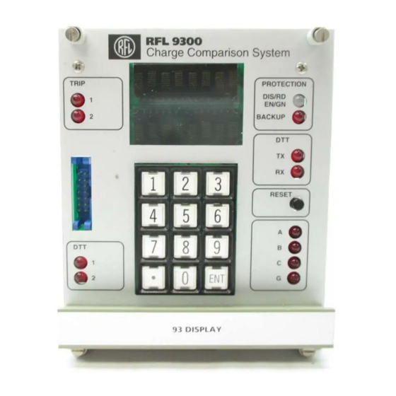
RFL Electronics RFL 9300 Instruction Manual (553 pages)
Charge Comparison System
Brand:
RFL Electronics
| Category:
Other
| Size: 29 MB
Table of Contents
Table of Contents
5
List of Illustrations
9
Section 1: Product Information
21
Section 2: System Operation
39
Introduction
39
System Initialization
39
Figure 2-1. Block Diagram, RFL 9300 Charge Comparison System (Two Terminal)
40
Communications Controller Module
42
Channel Impairment Characteristics
44
Table 2-1. Valid Hot-Standby Configurations
44
Supervisor Controller
47
Auxiliary Current Transformer (Act)
50
Phase Controllers
50
Figure 2-2. Logic Diagram, Composite Fault Detector
52
Figure 2-3. Logic Diagram, Strong-Feed Trips (for 2- and 3- Terminal Systems)
53
Figure 2-4. Differential Characteristics for 9300 in 2- and 3- Terminal Modes
54
Figure 2-5. Logic Diagram, Weak-Feed Trip (for 2- and 3- Terminal Systems)
56
Figure 2-6. Logic Diagram, Switch-Into-Fault with Communications (2- and 3- Terminal Systems)
57
Figure 2-7. Logic Diagram, Ultra High-Speed Trip
58
Figure 2-8. Logic Diagram for Open Conductor and Loss of Load Algorithm
59
Figure 2-9. Logic Diagram, Stub-Bus Applications
61
Backup Mode Operation
63
Figure 2-10. Logic Diagram, Switch-Into-Fault Without Communications
63
Direct Transfer Trip (Dtt)
64
Display Controller
64
Figure 2-11. Logic Diagram, Trip Seal-In
66
Figure 2-12. Logic Diagram, DTT Trip Seal-In
67
Oscillography Board
68
Irig-B
68
Diagnostics
68
Section 3: Applications
70
Introduction
70
Series Compensated Lines
70
Figure 3-1. Voltage Inversion
71
Figure 3-2. Phase Unbalance
71
Very Short Lines
72
Figure 3-3. High Source-To-Line Impedance Ratio
72
Effect of Infeed/Outfeed
73
Strong Bus Tie
73
Figure 3-4. Effect of Infeed/Outfeed
73
Figure 3-5. Strong Bus Tie
73
High-Resistance Ground Fault
74
Figure 3-6. High-Resistance Ground Fault with Heavy Through-Load, Causing an Outfeed Condition
74
Figure 3-7. Polar Diagram
74
Prefault Load Subtraction
75
Figure 3-8. Prefault Load Subtraction Eliminates Generator Angles
76
Figure 3-9. Currents before Pre-Fault Subtraction
77
Figure 3-10. Currents after Pre-Fault Subtraction
77
Ultra High-Speed Tripping
78
Figure 3- 11. Operation of the RFL 9300'S UHS Circuit During an Internal Fault
79
Figure 3-12. Operation of the RFL 9300'S UHS Circuit During and External Fault
79
Saturated Main Current Transformers
80
Figure 3-13. Saturated Main Current Transformers During Close-In Internal Fault
80
Figure 3-14. External Fault with very Severe CT Saturation at One End
82
Weak Infeed Applications
84
Figure 3-15. Weak Infeed Application
84
Reclose Blocking for Three-Phase Faults
85
Underground Cables
85
Figure 3-16. Double Line-To-Ground (DLG) Fault
86
Stub-Bus Protection
87
Figure 3-17. Sub-Bus Protection
88
Tapped Load
89
Figure 3-18. Typical Tapped Line Application
89
Figure 3-19. Transformer In-Rush
90
Figure 3-20. Zero-Sequence Current Flows through Transformer
91
Figure 3-21. Typical Tapped Line Application
91
Open Conductor with Single Line-To-Ground Fault
94
Figure 3-22. Open Conductor with Two Single-Line-To-Ground Faults (OC/2-SLG)
94
Figure 3-23. Open Conductor with One Single-Line-To-Ground Fault (OC/SLG)
95
SLG Fault Occurring on the Load Sending End Side of the Open Conductor
96
SLG Fault Occurring on the Load Receiving End Side of the Open Conductor
97
Open Conductor Without Single Line-To-Ground Fault
98
Figure 3-26. Open Conductor Without Single-Line-To-Ground Fault
98
Figure 3-27. Possible Miscoordination of Loss-Of-Load Plus Zone 2 Timer
99
Section 4: Setting Guidelines
100
Introduction
100
Programmable Parameters
100
Table 4-1. Programmable Parameters, RFL 9300 Two-Terminal Charge Comparison System
101
Table 4-2. Programmable Parameters, RFL 9300 Three-Terminal Charge Comparison System
102
Section 5: Installation
114
Introduction
114
Unpacking
114
Mounting
115
Figure 5-1. Mounting Dimensions of RFL 9300 Chassis Without Single Pole Option
116
Figure 5-2. Mounting Dimensions of RFL 9300 Chassis with Single Pole Option
117
Ventilation
118
Electrical Connections
118
Figure 5-3. Rear View, Typical RFL 9300 Charge Comparison System
119
Figure 5-4. Electrical Connections between RFL 9300 and Current Transformers on Protected Line
120
Figure 5-5. Electrical Connections between RFL 9300 with Optional Test Switch Chassis and Current Transformers on Protected Line
121
Figure 5-6. Overview of a Typical 9300 Two-Terminal Installation
122
Figure 5-7. Overview of a Typical RFL 9300 Three-Terminal Installation
122
Modem Connections
123
Fiber Optic Connections
124
Direct Digital Connections
124
Irig-B Clock Connections
124
Table 5-1. Pin Assignment for DC-37 Connector on RFL 93 DD I/O Direct Digital I/O Module
125
Section 6: Familiarization
126
Introduction
126
Controls and Indicators
126
Start-Up Procedures
126
Figure 6-1. Controls and Indicators, Typical Three-Terminal RFL 9300 Charge Comparison System
127
Table 6-1. Controls and Indicators, Typical Three-Terminal RFL 9300 Charge Comparison System
128
Figure 6-2. the RFL 9300 Keypad
129
Table 6-2. Keypad Functions, RFL 9300 Charge Comparison System
129
Table 6-3. RFL 9300 Module, General Information
130
Figure 6-3. RFL 9300 Module Position Numbers
131
Display Modes
139
Table 6-4. Alarm Codes for Two-Terminal and Three-Terminal RFL 9300 Charge Comparison System
140
Table 6-5. READ Mode Parameters for RFL 9300 Two-Terminal Charge Comparison Systems
144
Table 6-6. READ Mode Parameters for RFL 9300 Three-Terminal Charge Comparison Systems
146
Table 6-7. STARTUP Mode Parameters for RFL 9300 Two-Terminal Charge Comparison Systems
151
Table 6-8. STARTUP Mode Parameters for RFL 9300 Three-Terminal Charge Comparison Systems
151
Table 6-9. Programmable Parameters, RFL 9300 Two-Terminal Charge Comparison System
153
Table 6-10. Programmable Parameters, RFL 9300 Three-Terminal Charge Comparison System
154
Accessing the Rfl 9300 from a Pc or Terminal
157
Figure 6-4. Front Panel RS-232 Cable Connections
157
Figure 6-5. Cable Connections between RFL 9300 and PC or Terminal Using XON/XOFF Handshaking
158
Figure 6-6. APRIL Commands for Use with RFL 9300 (for Two-Terminal and Three-Terminal Mode)
160
Figure 6-7. Typical Alarm Display for Two-Terminal Mode
161
Figure 6-8. Typical Alarm Display for Three-Terminal Mode
162
Figure 6-9. Typical Values Display for Two-Terminal Mode
164
Figure 6-10. Typical Values Display for Three-Terminal Mode
164
Figure 6-11. Typical Read Settings Menu for Two-Terminal Single-Pole Mode
166
Figure 6-12. Typical Read Settings Menu for Two-Terminal Three-Pole Mode
167
Figure 6-13. Typical Read Settings Menu for Three-Terminal Single-Pole Mode
168
Figure 6-14. Typical Read Settings Menu for Three-Terminal Three-Pole Mode
168
Figure 6-15. Typical Configuration and Software Version Display for Two-Terminal and Three-Terminal Systems
169
Figure 6-16. Typical Remote Parameters Display for a Two-Terminal Single-Pole System
170
Figure 6-17. Typical Remote Parameters Display for a Two-Terminal Three-Pole System
170
Figure 6-18. Typical Remote Parameters Display for a Three-Terminal Single-Pole System
171
Figure 6-19. Typical Remote Parameters Display for a Three-Terminal Three-Pole System
172
Figure 6-20. Typical UPDATE Screen for a Two-Terminal System
176
Figure 6-21. Typical UPDATE Screen for a Three-Terminal System
176
Figure 6- 22. Sequence of Events Menu
177
Figure 6-23. Typical Alarm Sequence of Events Display
178
Figure 6-24. Typical Alarm Sequence of Events Display
178
Figure 6-25. Typical Trip Sequence of Events Display
179
Figure 6-26. Typical Oscillography Data Table
179
Figure 6-27. a Typical Oscillography Data Plot
181
Figure 6-28. Typical Programming Menu
182
Figure 6-29. Typical Parameter Settings List for a Three-Terminal System
183
Rfl 9300 Addressing
186
Figure 6-30. a Typical Two-Terminal Installation Where Addressing Is Required
186
Figure 6-31. a Typical Two-Terminal Installation Where Addressing Is Not Required
187
Figure 6-32. Typical RFL 9300 Three-Terminal Addressing Scheme
188
DESCRIPTION of INSTANTANEOUS OVERCURRENT BACKUP TRIP ALGORITHM and INVERSE TIME OVERCURRENT BACKUP TRIP ALGORITHM
189
Time-Overcurrent Curve Equations
192
Section 7: Laboratory Acceptance Tests
202
Introduction
202
Equipment Requirements
202
System Setup
203
Figure 7-1. Back-To-Back Relay, Test Setups
204
Test Procedures
205
Figure 7-2. Test Connections Simulating an External A-G Fault
209
Figure 7-3. Test Connections Simulating an External A-B Fault
211
Figure 7-4. Test Connections Simulating an External Three-Phase Fault
211
Figure 7-5. Phasor Diagram, Single-Phase Test Simulation of an External Three-Phase Fault
212
Figure 7-6. Phasor Diagram, Real External Three-Phase Fault
212
Figure 7-7. Test Connections Simulating an Internal A-G Fault
213
Figure 7-8. Test Connections Simulating an Internal A-B Fault
216
Figure 7-9. Test Connections Simulating an Internal Three-Phase Fault
217
Figure 7-10. Test Connections Simulating an Internal A-G Fault with Weak Infeed at the Right Terminal
218
Figure 7-11. Test Connections Simulating an Internal A-G Fault with Breaker Open at the Right Terminal
220
Figure 7-12. Test Connections for Oscillography Test
222
Figure 7-13. Oscillography Test Data Plot
223
Section 8: Field Commissioning
224
Introduction
225
SINGLE-RELAY TESTS (Optional)
225
Figure 8-1. Single Relay Test Setups
227
Table 8-1. Programmable Parameters, RFL 9300 Two-Terminal Charge Comparison System
231
Table 8-2. Programmable Parameters, RFL 9300 Three-Terminal Charge Comparison System
232
Figure 8-2. Test Connections Simulating an Internal A-G Fault
235
Figure 8-3. Test Connections Simulating an Internal A-B Fault
238
Figure 8-4. Test Connections Simulating an Internal Three-Phase Fault
239
Verification of End-To-End Communications
241
Table 8-3. Acceptable Received Fiber Optic Power Levels, RFL 9300 Charge Comparison System
243
Startup Mode
245
Table 8-4. STARTUP Mode Parameters for RFL 9300 Two-Terminal Charge Comparison Systems
248
Table 8-5. STARTUP Mode Parameters for RFL 300 Three-Terminal Charge Comparison Systems
248
Figure 8-5. Electrical Connections between RFL 9300 and Current Transformers on Protected Line
250
Figure 8-6. Correctly Wired Two-Terminal System
254
Figure 8-7. Phase Inversion at Remote 1 Relay
254
Figure 8-8. Phase Inversion at Local Relay
255
Figure 8-9. Correctly Wired Three-Terminal System
256
Figure 8-12. Phase Inversion at Local Station
259
Final Commissioning
261
Section 9: Display Module
262
Introduction
262
Display Controller Board
262
Figure 9-1. RFL 9300 Display Module for Horizontal Chassis
262
Table 9-1. RFL 93B Display Module, General Information
263
Figure 9-2. Controls and Indicators for Display Controller Board, Used in RFL 9300 Display Module
264
Oscillography Board
267
Figure 9-3. Controls and Indicators for Oscillography Board, Used in RFL 93B DISPLAY Module
268
Front Panel
270
Figure 9-4. Component Locator Drawing for Display Controller Board, Used in RFL 9300 Display Module
273
Description
274
Table 9-3. Replaceable Parts for Oscillography Board, Used in RFL 9300 Display Modules (Assembly No. 106330)
274
Description
275
Figure 9-5. Component Locator Drawing for Oscillography Board, Used in RFL 9300 Display Module
276
Description
277
Table 9-4. Replaceable Parts for Front Panel Assembly, Used in RFL 9300 Display Module (Assembly No. 106335)
277
Figure 9-6. Component Locator Drawing for Front Panel Assembly, Used in RFL 9300 Display Module
278
Figure 9-7. Oscillography Board, Part of RFL 9300 Display Module (Assembly No. 106330; Schematic No. D-106764-A)
279
Figure 10-1. RFL 9300 Supervisor Controller Module
280
Figure 10-2. Controls and Indicators, RFL 9300 Supervisor Controller Module
281
Figure 10-3. Component Locator Drawing, Supervisor Controller Modules for RFL 9300
291
Figure 10-4. Supervisor Controller Module for RFL 9300 Charge Comparison System
292
Figure 11-1. RFL 93B ACT I/O Auxiliary Current Transformer I/O Module
293
Figure 11-2. Controls and Indicators, RFL 93B ACT I/O Auxiliary Current Transformer I/O Module
294
Figure 11-3. Block Diagram, RFL 93B ACT I/O Auxiliary Current Transformer I/O Module
295
Table 11-1. Replaceable Parts, RFL 93B ACT-5 5-Ampere Auxiliary Current Transformer to I/O Module
296
Figure 11-4. Component Locator Drawing, RFL 93B ACT-5 5-Ampere Auxiliary Current Transformer I/O Module
298
Figure 11-5. RFL 93B ACT-5 5-Ampere Auxiliary Current Transformer I/O Module (Assembly No. 106345; Schematic No. D-105814, Rev. C)
299
Figure 12-1. RFL 9300 Phase Controller Module
301
Figure 12-2. Controls and Indicators, RFL 9300 Phase Controller Modules
302
Table 12-1. Replaceable Parts, Phase Controller Modules for RFL 9300 Charge Comparison System
305
Figure 12-3. Component Locator Drawing, Phase Controller Modules for RFL 9300 Charge Comparison System
307
Figure 12-4. Phase Controller Modules for RFL 9300 Charge Comparison System
308
Figure 13-1. RFL 9300 Communications Controller Module
309
Figure 13-2. Controls and Indicators, RFL 9300 Communications Controller Module
310
Figure 13-3. Block Diagram, RFL 9300 Communications Controller Module
312
Figure 13-4. Transmitter Timing Diagram, RFL 9300 Communications Controller Module
315
Figure 13-5. Receiver Timing Diagram, RFL 9300 Communications Controller Module
316
Figure 13-6. Logic Diagram for Programmable Logic Device U24
318
Table 13-1. Replaceable Parts, Communications Controller Modules for RFL 9300 Charge Comparison System
319
Figure 13-7. Component Locator Drawing, Communications Controller Module for RFL 9300
321
Figure 13-8. Communications Controller Modules for RFL 9300 Charge Comparison System
322
Figure 14-1. RFL 9300 Modem Module
323
Figure 14-2. Controls and Indicators, RFL 9300 Modem Module
324
Table 14-1. Replaceable Parts, Modem Modules for RFL 9300 Charge Comparison System
328
Figure 14-3. Component Locator Drawing, Modem Module for RFL 9300 Charge Comparison System
330
Figure 14-4. Modem Module for RFL 9300 Charge Comparison System
331
103829, Rev. B)
331
Section 15: Line Coupler I/O Module
333
Description
333
Controls and Indicators
333
Figure 15-1. RFL 93 LC I/O Line Couple I/O Module
333
Theory of Operation
334
Table 15-1. Replaceable Parts, RFL 93 LC I/O Line Coupler I/O Module
334
Figure 15-2. Component Locator Drawing, RFL 93 LC I/O Line Couple I/O Module
335
Figure 15-3. RFL 93 LC I/O Line Coupler I/O Module
336
Section 16: Direct Digital Interface I/O Module
337
Description
337
Controls and Indicators
337
Figure 16-1. RFL 93 DD I/O Direct Digital Interface I/O Module
337
Figure 16-2. Controls and Indicators, RFL 93 DD Direct Digital I/O Module
338
Theory of Operation
339
Table 16-1. Replaceable Parts, RFL 93 DD I/O Direct Digital Interface I/O Module
340
Figure 16-3. Component Locator Drawing, RFL 93 DD I/O Direct Digital I/O Module
341
Figure 16-4. RFL 93 DD I/O Direct Digital I/O Module (Assembly No. 103830-1; Schematic No. D-103834-1, Rev. A)
342
Section 17: Single Width Fiber Optic Transceiver Module
343
Introduction
343
Figure 17-1. RFL 93 B FT/FR Single Width Fiber Optic Transceiver Module
343
Description
344
Specifications
344
Controls and Indicators
346
Figure 17-2. Controls and Indicators, RFL 93B FT/FR Single Width Fiber Optic Transceiver Mode
347
Theory of Operation
348
Figure 17-3. Block Diagram, RFL 93B FT/FR Single Width Fiber Optic Transceiver Module
349
Figure 17-4. RFL 9300 Fiber Optics Hot Standby Signal Routing Diagram
350
Table 17-1. Replaceable Parts, RFL 93B FT/FR Single Width Fiber Optic Transceiver Module
351
Figure 17-5. Component Locator Drawing, RFL 93B FT/FR Single Width Fiber Optic Transceiver Module
353
Figure 17-6. RFL 93 FT/FR Singlewidth Fiber Optic Transceiver Module (Assembly No. 106360; Schematic No. D- 105849, Rev. B)
354
Section 18: Single Width Fiber Optic I/O Module
355
Introduction
356
Figure 18-1. Typical RFL 93 FT/FR Single Width Fiber Optic I/O Module
356
Description
357
Specifications
357
Table 18-1. Differences between Single Width Fiber Optic I/O Modules
357
Controls and Indicators
358
Figure 18-2. Controls and Indicators, RFL 93 FT/FR I/O-8M Single Width Fiber Optic I/O Module
358
Figure 18-3. Controls and Indicators, RFL 93 FT/FR I/O-13S and 13 M Single Width Fiber Optic I/O Modules
359
Figure 18-4. Controls and Indicators, RFL 93 FT/FR I/O-13SL and 15SL Single Width Fiber Optic I/O Modules
360
Theory of Operation
361
Figure 18-5. Block Diagram, RFL 93 FT/FR I/O-8M 850 Nm Multimode Fiber Optic I/O Module
361
Figure 18-6. Block Diagram, RFL 93 FT/FR-13M (Multimode) and RFL 93 FT/FR-S (Singlemode) 1300-Nm Fiber Optic I/O Module
363
Figure 18-7. Block Diagram, RFL 93 FT/FR 13SL (1300-Nm Singlemode) and RFL 93 FT/FR 15SL (1550-Nm Singlemode)
365
Table 18-2. Replaceable Parts, RFL 93 FT/FR I/O-8M Singlewidth Fiber Optic I/O Module
367
Figure 18-8. Component Locator Drawing, RFL 93 FT/FR I/O-8M 850-Nm Multimode Singlewidth Fiber Optic I/O Module (Assembly No. 105850; Drawing No. 105853-A)
369
Figure 18-9. RFL 93 FT/FR Singlewidth Fiber Optic I/O Module -8M (Assembly No. 105850; Schematic No. D-105854, Rev. D)
370
Table 18-3. Replaceable Parts, RFL 93 FT/FR I/O Singlewidth Fiber Optic I/O Modules
371
Figure 18-11. RFL 93 FT/FR Singlewidth Fiber Optic I/O Modules, -13M (Assembly No. 105855; Schematic No. D- 105864, Rev. A), -13S (Assembly No. 105860; Schematic No. D-105864, Rev. A)
374
Table 18-4. Replaceable Parts, Singlewidth Fiber Optic I/O Modules
375
Figure 18-12. Component Locator Drawing, RFL 93 FT/FR I/O-13SL and RFL 93 FT/FR I/O-15SL
377
Figure 18-13. RFL 93 FT/FR Singlewidth Fiber Optic I/O Modules, -13SL (Assembly No. 105865; Schematic No. D- 105869, Rev. A), -15SL (Assembly No. 105870; Schematic No. D-105869, Rev. A)
378
Section 19: Power Supply Module
379
Description
379
Figure 19-1. Typical RFL 9300 Power Supply Module
379
Specifications
380
Table 19-1. 9300 Power Supply Specifications
380
Theory of Operation
381
Table 19-2. Replaceable Parts, 50-Watt Power Supply Module for RFL 9300 Charge Comparison System
382
Figure 19-2. Component Locator Drawings, 50-Watt Power Supply Module
384
Figure 19-3. 9300 PS 48/125 DC Power Supply Module for RFL 9300 Charge Comparison System
385
106715-1; Schematic No. 106719-E)
385
Section 20: Relay I/O Module
387
Description
387
Controls and Indicators
387
Figure 20-1. RFL 93B Relay I/O Module, Rear Panel
387
Figure 20-2. Rear Panel Connectors and Terminal Blocks, RFL 93B Relay I/O Module
388
Figure 20-3. Controls and Indicators, Power/Rf-232 Board for RFL 93B Relay I/O Module
389
Theory of Operation
391
Table 20-1. Replaceable Parts, RFL 93B Relay I/O, Power/Rs-232 Board
393
Figure 20-4. Component Locator Drawing, RFL 93B Relay I/O Module, Power/Rs-232 Board
394
Table 20-2. Replaceable Parts, RFL 93 Relay I/O Module, Current Sense Board
395
Figure 20-5. Component Locator Drawing, RFL 93B Relay I/O Module, Current Sense Board
396
Table 20-3. Replaceable Parts, RFL 93 Relay I/O Module, Relay Output Board
397
Figure 20-6. Component Locator Drawing, RFL 93B Relay I/O Module, Relay Output Board
398
Figure 20-7. RFL 93B RELAY I/O Module, Power/Rs-232 Board
399
Section 21. Alarm I/O Module
401
Description
401
Controls and Indicators
401
Figure 21-1. RFL 93 Alarm I/O Module
401
Figure 21-2. Controls and Indicators, RFL 93 Alarm I/O Module
402
Theory of Operation
404
Table 21-1. Replaceable Parts, RFL 93 Alarm I/O Module
405
Table 21-2. Replaceable Parts, RFL 93 Alarm I/O Module
406
Figure 21-3. Component Locator Drawing, RFL 93 Alarm I/O Module
408
Section 22. Short Haul Fiber Interface Module and Fiber Service Unit
409
Introduction
410
Figure 22-1. Front Panel View of RFL 93 SH FIBER Short Haul Interface Module and RFL FSU Fiber Service Unit
410
Short Haul Fiber Interface Module
411
Table 22-1. General Information, Short Haul Fiber Interface Module
411
Figure 22-2. Controls and Indicators, RFL 93 SHFI Short Haul Fiber Interface Module
412
Fiber Service Unit
413
Figure 22-3. Typical Fiber Service Unit Installation
413
Table 22-2. Replaceable Parts, RFL 93 SHFI Short Haul Fiber Interface Module
414
Figure 22-4. Component Locator Drawing, RFL 93 Short Haul Fiber Interface Module (Assembly No. 107500)
416
Figure 22-5. Schematic, RFL 93 Short Haul Fiber Module (3 Sheets) (Assembly No. 107500; Schematic No. D-107504-C)
417
Section 23: G.703 Interface I/O Module
419
Description
419
Controls and Indicators
419
Figure 23-1. RFL 93 G.703 Interface I/O Module
419
Figure 23-2. Controls and Indicators, RFL 93 G.703 Interface I/O Module
420
Theory of Operation
421
Figure 23-3. Setting J5 for Normal or Loops Operation
422
Table 23-1. Replaceable Parts, RFL 93 G.703 Interface I/O Module
424
Figure 23-4. Component Locator Drawing, RFL 93 G. 703 Interface I/O Module
426
Figure 23-5. Schematic, RFL 93 G.703 Module (Assembly No. 106730; Drawing No. D-106734-B)
427
Section 24: Single Pole Chassis
429
Description
429
Conrols and Indicators
429
Figure 24-1. Typical RFL 9300 Single Pole Chassis, Front Panel View
429
Table 24-1. RFL 9300 Single Pole Chassis, General Information
429
Figure 24-2. Typical RFL 9300 Single Pole Chassis, Front Panel View Showing LED Indicators
430
Figure 24-3. Typical RFL 9300 Single Pole Chassis, Rear Panel View
431
Theory of Operation - Hardware
434
Theory of Operation - Software
436
Figure 24-4. Target Message Word Sent from the Display Controller to the Single-Pole Chassis
436
Figure 24-5. 16-Bit Status Messages Transmitted by the Single-Pole Logic to the Supervisor at 250Ms Intervals
437
Table 24-2. Replaceable Parts, RFL 9300 Single Pole Chassis
440
Figure 24-6. Component Locator Drawing, RFL 9300 Single Pole Chassis, Main Circuit Board
441
Table 24-3. Replaceable Parts, RFL 9300 Single Pole Chassis, Rear Panel Assembly
443
Figure 24-8. Component Locator Drawing, RFL 9300 Single Pole Chassis, Rear Panel
444
Figure 24-9. Schematic, 9300 Single Pole Chassis, Rear Panel (Drawing No. D-106709-C)
445
Section 25. Chassis and Front Panel Rs-232 Module
447
Description
447
Figure 25-1. Typical RFL 9300 Chassis
447
Figure 25-2. Block Diagram of RS-232 Front Board
448
Table 25-1. Replaceable Parts, RFL 93 INTER Interconnected Motherboard
449
Figure 25-3. Component Locator Drawing, RFL 93 INTER Interconnect Motherboard
450
Figure 25-4. RFL 93 INTER Interconnect Motherboard (Assembly No. 103905-1; Schematic No. D-103909-1-D)
451
Figure 25-5. Component Locator Drawing, RFL 9300 Front Panel RS-232 Module
452
Table 25-2. Replaceable Parts, RFL 9300 Front Panel RS-232 Interface Module
452
Figure 25-6. RS-232 Front Panel Interface (Assembly No. 106755; Schematic No. C-106759-B)
453
Section 26: Expansion Chassis
455
Figure 26-1. Typical RFL 9300 Expansion Chassis, Rear View
455
Table 26-1. Expansion Chassis, General Information
455
Figure 26-2. Component Locator Drawing, RFL 9300 Expansion Chassis Power Supply (Assembly No. 106350)
456
Table 26-2. Replaceable Parts, RFL 9300 Expansion Chassis Power Supply
456
Figure 26-3. Schematic, Power Converter I/O - 250 VDC, for RFL 9300 Charge Comparison System
457
Section 27. Protocol Converters
459
Description
459
Configurations
459
Table 27-1. Protocol Converters Currently Available
459
Converter Operation
460
9300 Setup
460
Converter Address Selection
460
Specifications
460
Connections
461
Cables
461
Terminal Block Pinouts
461
Block Diagram
462
Figure 27-1. Protocol Converter Block Diagram
462
MODBUS MAP (Version A3, M13, 9/12/01)
463
Table 27-2. Modbus Map
463
Table 27-3. Modbus RTU Format Table
467
Dnp Profile Document
468
DNP POINT LIST (Version A1,M13,8/3/01)
470
Table 27-4. POINT LIST FOR: 16 Bit Analog Without Flag (Object 30 Var 4)
470
Table 27-5. POINT LIST FOR: Binary Input Change with Tim (Object 02 Var 2)
471
Table 27-6. POINT LIST FOR: 16 Bit Analog with Time (Object 32 Var 4)
472
Table 27-7. POINT LIST FOR: 16 Bit Analog Output Status (Object 40 Var 2)
472
Table 27-8. Format Table
473
Section 28. Maintenance
475
Introduction
475
Alarm Codes
475
Removal and Replacement
477
Fuse Replacement
479
Corrective Maintenance
480
How to Arrange for Servicing
480
Table 28-1. Fuse Replacement Data, RFL 9300 Power Supply Module
480
Instructions for Converting a 3-Terminal 9300 to a 2-Terminal 9300
481
Section 29: Modem Application Information
483
Introduction
483
Transmitter Levels and Wiring
483
Receiver Levels and Wiring
483
S/N Ratio Vs Dependability
483
Figure 29-1. RFL 9300 Modem Dependability Versus S/N Ratio (Measured)
484
Telephone Service Requirements
485
Microwave, Radio, and T1 Analog Channels
485
Channel Routing Vs Dependability
485
Modem Security
485
Squelch Rules
485
Figure 29-2. RFL 9300 Probability of Passing False Words (Theoretical)
486
Figure 29-3. RFL 9300 Modem Security (Theoretical)
487
Channel Delay Limits
488
Test Points
489
Section 30: Glossary of Terms
491
Section 31: Index
497
Section 32: Schematics
503
Advertisement
Advertisement
Related Products
RFL Electronics RFL 9660
RFL Electronics RFL3200 UK-10
RFL Electronics Categories
Multiplexer
Media Converter
Network Router
Switch
Computer Hardware
More RFL Electronics Manuals
Login
Sign In
OR
Sign in with Facebook
Sign in with Google
Upload manual
Upload from disk
Upload from URL