Sign In
Upload
Manuals
Brands
Reymsa Manuals
Accessories
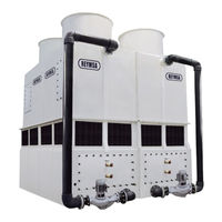
HFC-SL-822-LS Series
Reymsa HFC-SL-822-LS Series Manuals
Manuals and User Guides for Reymsa HFC-SL-822-LS Series. We have
1
Reymsa HFC-SL-822-LS Series manual available for free PDF download: Installation, Operation & Maintenance Manual
Reymsa HFC-SL-822-LS Series Installation, Operation & Maintenance Manual (72 pages)
All-Fiberglass Cooling Towers
Brand:
Reymsa
| Category:
Accessories
| Size: 10 MB
Table of Contents
Table of Contents
4
Installation
7
Location
7
Recirculation and Interference
7
Table A-1: Minimum Recommended Distance between Towers
7
Figure A-1: Minimum Recommended Distance between Towers
7
Environmental and Safety
8
Figure A-2: Recirculation
8
Assembly Instructions
9
Figure A-3: Single Fan Tower Fork Lifting
9
Figure A-4: Single Fan Tower Crane Lifting
9
Figure A-5: Fan Duct Lifting
9
Single Fan Towers
9
Figure A-6: Typical Anchorage for a Single Fan Tower
10
Figure A-7: Upper and Lower Parts Installation
10
Table A-2: Receiving Flange Type (Single Fan Towers)
11
Figure A-8: Fan Duct Assembly for a Single Tower
11
Figure A-9: Fan Duct Alignment for a Single Tower
11
Double Fan Towers
12
Figure A-10: Double Fan Tower Fork Lifting
12
Figure A-11: Double Fan Tower Crane Lifting
12
Figure A-12: Fan Duct Lifting
12
Figure A-13: Basin Lifting (Optional)
13
Figure A-14: Typical Anchorage for a Double Fan Tower
13
Figure A-15: Fan Duct, Upper and Lower Parts Installation
13
Table A-3: Receiving Flange Type (Double Fan Towers)
14
Figure A-16: Fan Duct Assembly for a Double Fan Tower
14
Figure A-17: Fan Duct Alignment for a Double Fan Tower
14
Figure A-18: Double Fan Tower Fork Lifting
15
Figure A-19: Double Fan Tower Crane Lifting
15
Figure A-20: Fan Duct Lifting
15
Quadruple Fan Towers
15
Figure A-21: Basin Lifting (Optional)
16
Figure A-22: Typical Anchorage for a Quadruple Fan Tower
16
Figure A-23: Lower Section Installation for Quadruple Fan Tower
16
Figure A-24: Upper Section 1 Quadruple Fan Tower
16
Figure A-25: Upper Section 1 & 2 for a Quadruple Fan Tower on Plane
17
Table A-4: Receiving Flange Type (Quadruple Fan Towers)
18
Figure A-26: Fan Duct Installation for a Quadruple Fan Tower
18
Figure A-27: Fan Duct Alignment for a Quadruple Fan Tower
18
Figure A-28: Lifting for HFC-F Models
19
Figure A-29: Typical Anchorage for HFC-F Models
19
Single Fan Tower (Gear Driven Models)
19
Figure A-30: Upper Body Section Installation for HFC-F Models
20
Figure A-31: Fan Duct Assembly for HFC-F Models
20
Figure A-32: Screen Mesh Assembly for HFC-F Models
20
Spray Pump
21
Table A-5: Flanges Recommended Torque
21
Figure A-33: Spray Pump and Water Return Pipes Assembly to Tower
21
Copper Coil Unit
22
Figure A-34: Copper Coil Unit
22
Figure A-35: Fan Adaptor in a Single Fan Tower
23
Figure A-36: Fan Adaptor Installation
23
Figure A-37: Fan Adaptor Alignment
23
Low Sound Fan Closed Circuit Fluid Cooler: Fan Adaptors
23
Figure A-38: Fan Adaptor 2 Installation
24
Figure A-39: Fan Duct Installation on a Fan Adaptor
24
Figure A-40: Fan Duct Alignment
24
Figure A-41: Fan Duct Installation in a Fan Adaptor for a Quadruple Fan Tower
24
Optional Accessories
25
Accessories - Safety
25
Figure A-42: Optional Accessories by REYMSA
25
Figure A-43: Optional Safety Accessories
26
Figure A-44: Vibration Switch Recommended Location
27
Figure A-45: Internal Switches
27
Figure A-46: Typical Electric Diagram
27
Vibration Switch
27
Figure A-47: Vibration Switch Detail
28
Figure A-48: Sensitivity Adjustment
28
Basin Heater
29
Figure A-49: Basin Heater System
29
Figure A-50: Recommended Basin Heater Mounting
29
Figure A-51: Basin Heater Control Panel Diagram
30
Electric Water Level Control System
31
Figure A-52: Electrical Water Level Control System
31
Figure A-53: Electrical Connections & Water Level Control Parts
31
Figure A-54: Motor Shaft Grounding Ring
32
Figure A-55: Motor Shaft Grounding Ring Path to Ground
32
Motor Shaft Grounding Ring
32
Tower Set-Up
33
Figure A-56: Example of a Base Support
33
Leveling and Tower Supports
33
Piping Connections
33
Figure A-57: Pipe Connections for a Single Fan Tower
34
Figure A-58: Pipe Connections for a Double Fan Tower
34
Figure A-59: Pipe Connections for a Quadruple Fan Tower
35
Procedure to Wire the Spray Pump Motor
36
Wiring
36
Procedure to Wire the Fan Motor
37
Start-Up
38
Filling System with Water
38
Controlling Water Level
38
Table B-1: Operation and Start-Up Basin Level
38
Figure B-1: Float Valve Installation
38
Gear Reducer
39
Spray Pump
39
Fan
40
Operation
41
Fan Control - Vfd
41
Parameters for Vfd Operation
41
Figure C-1: VFD Operation Range
41
Configuration and Start-Up for Abb Ach550-Uh
42
Figure C-2: Start-Stop Method
42
Figure C-3: Operation Method
42
Figure C-4: Measuring Range RTD
42
Figure C-5: Recommended Connection Diagram for ABB ACH550-UH
42
Water Distribution System
45
Table C-1: Maximum Operating Temperatures
45
Table C-2: Maximum Operating Pressure
45
Figure C-6: Water Distribution System Schematic Drawing
45
Water Treatment and Water Chemestry
46
Table C-3: Water Chemistry Guidelines
46
Figure C-7: Chemical Treatment Connection Installation
46
Biological Growth
47
Figure C-8: Filtration System
47
Scale Formation
47
Suspended Solids
47
Air Pollution
48
Corrosion
48
Make-Up Water Requirements
48
Table C-4: Cycle of Concentration
48
Cold Weather Operation
49
Basin Heater Operation
50
Coil Freezing Protection
50
Pump Freezing Protection
50
Remote Sump Operation
50
Table C-5: Recommended Solution Freezing Protection Temperature
50
Seasonal Shut-Down
51
Figure C-9: Fan Discharge Covering
51
Maintenance
52
Tower Maintenance Schedule
53
Table D-1: Recommended Tower and Optional Equipment Maintenance Schedule
53
Basin
54
Tower Body
55
Fan Motor
56
Gear Reducer
58
Table D-2: Oil Capacity for Gear Reducer Models
58
Basin Heater
59
Spray Pump
60
Figure D-1: Lubrication Points
60
Copper Coil Unit
61
Table D-3: Copper Coil Unit(S) Weight by Model
61
Figure D-2: Copper Coil Unit Pulled out for Maintenance Purpose When Tower Is on the Ground
61
Figure D-3: Copper Coil Unit Pulled out for Maintenance Purpose When Tower Is on the Roof
61
Trouble-Shooting
62
Appendix A: Example of Structural Base for a Reymsa Closed Circuit Fluid Cooler
64
Appendix B: Examples of Accessories Assembly Instructions
67
Appendix C: Minimum Distance between Towers and Obstructions
69
Appendix D: Water Make-Up Float Valve
70
Figure AP-1: Float Valve Parts
70
Advertisement
Advertisement
Related Products
Reymsa HFC-SL-810-LS Series
Reymsa HFC-SL-808-LS Series
Reymsa HFC-SL-812-LS Series
Reymsa HFC-SL-819-LS Series
Reymsa HFC-SL-816-LS Series
Reymsa HFC-SL-827-LS Series
Reymsa HFC-SL-1414-LS Series
Reymsa HFC-SL-1619-LS Series
Reymsa HFC-SL-1627-LS Series
Reymsa HFC Series
Reymsa Categories
Fan
Accessories
More Reymsa Manuals
Login
Sign In
OR
Sign in with Facebook
Sign in with Google
Upload manual
Upload from disk
Upload from URL