Sign In
Upload
Manuals
Brands
Reymsa Manuals
Accessories
HFC-1619 Series
Reymsa HFC-1619 Series Fluid Cooler Manuals
Manuals and User Guides for Reymsa HFC-1619 Series Fluid Cooler. We have
1
Reymsa HFC-1619 Series Fluid Cooler manual available for free PDF download: Installation, Operation & Maintenance Manual
Reymsa HFC-1619 Series Installation, Operation & Maintenance Manual (72 pages)
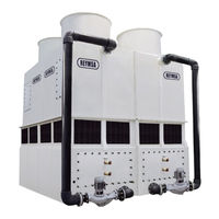
All-Fiberglass Cooling Towers
Brand:
Reymsa
| Category:
Accessories
| Size: 10 MB
Table of Contents
Table of Contents
4
Installation
7
Location
7
Recirculation and Interference
7
Table A-1: Minimum Recommended Distance between Towers
7
Figure A-1: Minimum Recommended Distance between Towers
7
Environmental and Safety
8
Figure A-2: Recirculation
8
Assembly Instructions
9
Figure A-3: Single Fan Tower Fork Lifting
9
Figure A-4: Single Fan Tower Crane Lifting
9
Figure A-5: Fan Duct Lifting
9
Single Fan Towers
9
Figure A-6: Typical Anchorage for a Single Fan Tower
10
Figure A-7: Upper and Lower Parts Installation
10
Table A-2: Receiving Flange Type (Single Fan Towers)
11
Figure A-8: Fan Duct Assembly for a Single Tower
11
Figure A-9: Fan Duct Alignment for a Single Tower
11
Double Fan Towers
12
Figure A-10: Double Fan Tower Fork Lifting
12
Figure A-11: Double Fan Tower Crane Lifting
12
Figure A-12: Fan Duct Lifting
12
Figure A-13: Basin Lifting (Optional)
13
Figure A-14: Typical Anchorage for a Double Fan Tower
13
Figure A-15: Fan Duct, Upper and Lower Parts Installation
13
Table A-3: Receiving Flange Type (Double Fan Towers)
14
Figure A-16: Fan Duct Assembly for a Double Fan Tower
14
Figure A-17: Fan Duct Alignment for a Double Fan Tower
14
Figure A-18: Double Fan Tower Fork Lifting
15
Figure A-19: Double Fan Tower Crane Lifting
15
Figure A-20: Fan Duct Lifting
15
Quadruple Fan Towers
15
Figure A-21: Basin Lifting (Optional)
16
Figure A-22: Typical Anchorage for a Quadruple Fan Tower
16
Figure A-23: Lower Section Installation for Quadruple Fan Tower
16
Figure A-24: Upper Section 1 Quadruple Fan Tower
16
Figure A-25: Upper Section 1 & 2 for a Quadruple Fan Tower on Plane
17
Table A-4: Receiving Flange Type (Quadruple Fan Towers)
18
Figure A-26: Fan Duct Installation for a Quadruple Fan Tower
18
Figure A-27: Fan Duct Alignment for a Quadruple Fan Tower
18
Figure A-28: Lifting for HFC-F Models
19
Figure A-29: Typical Anchorage for HFC-F Models
19
Single Fan Tower (Gear Driven Models)
19
Figure A-30: Upper Body Section Installation for HFC-F Models
20
Figure A-31: Fan Duct Assembly for HFC-F Models
20
Figure A-32: Screen Mesh Assembly for HFC-F Models
20
Spray Pump
21
Table A-5: Flanges Recommended Torque
21
Figure A-33: Spray Pump and Water Return Pipes Assembly to Tower
21
Copper Coil Unit
22
Figure A-34: Copper Coil Unit
22
Figure A-35: Fan Adaptor in a Single Fan Tower
23
Figure A-36: Fan Adaptor Installation
23
Figure A-37: Fan Adaptor Alignment
23
Low Sound Fan Closed Circuit Fluid Cooler: Fan Adaptors
23
Figure A-38: Fan Adaptor 2 Installation
24
Figure A-39: Fan Duct Installation on a Fan Adaptor
24
Figure A-40: Fan Duct Alignment
24
Figure A-41: Fan Duct Installation in a Fan Adaptor for a Quadruple Fan Tower
24
Optional Accessories
25
Accessories - Safety
25
Figure A-42: Optional Accessories by REYMSA
25
Figure A-43: Optional Safety Accessories
26
Figure A-44: Vibration Switch Recommended Location
27
Figure A-45: Internal Switches
27
Figure A-46: Typical Electric Diagram
27
Vibration Switch
27
Figure A-47: Vibration Switch Detail
28
Figure A-48: Sensitivity Adjustment
28
Basin Heater
29
Figure A-49: Basin Heater System
29
Figure A-50: Recommended Basin Heater Mounting
29
Figure A-51: Basin Heater Control Panel Diagram
30
Electric Water Level Control System
31
Figure A-52: Electrical Water Level Control System
31
Figure A-53: Electrical Connections & Water Level Control Parts
31
Figure A-54: Motor Shaft Grounding Ring
32
Figure A-55: Motor Shaft Grounding Ring Path to Ground
32
Motor Shaft Grounding Ring
32
Tower Set-Up
33
Figure A-56: Example of a Base Support
33
Leveling and Tower Supports
33
Piping Connections
33
Figure A-57: Pipe Connections for a Single Fan Tower
34
Figure A-58: Pipe Connections for a Double Fan Tower
34
Figure A-59: Pipe Connections for a Quadruple Fan Tower
35
Procedure to Wire the Spray Pump Motor
36
Wiring
36
Procedure to Wire the Fan Motor
37
Start-Up
38
Filling System with Water
38
Controlling Water Level
38
Table B-1: Operation and Start-Up Basin Level
38
Figure B-1: Float Valve Installation
38
Gear Reducer
39
Spray Pump
39
Fan
40
Operation
41
Fan Control - Vfd
41
Parameters for Vfd Operation
41
Figure C-1: VFD Operation Range
41
Configuration and Start-Up for Abb Ach550-Uh
42
Figure C-2: Start-Stop Method
42
Figure C-3: Operation Method
42
Figure C-4: Measuring Range RTD
42
Figure C-5: Recommended Connection Diagram for ABB ACH550-UH
42
Water Distribution System
45
Table C-1: Maximum Operating Temperatures
45
Table C-2: Maximum Operating Pressure
45
Figure C-6: Water Distribution System Schematic Drawing
45
Water Treatment and Water Chemestry
46
Table C-3: Water Chemistry Guidelines
46
Figure C-7: Chemical Treatment Connection Installation
46
Biological Growth
47
Figure C-8: Filtration System
47
Scale Formation
47
Suspended Solids
47
Air Pollution
48
Corrosion
48
Make-Up Water Requirements
48
Table C-4: Cycle of Concentration
48
Cold Weather Operation
49
Basin Heater Operation
50
Coil Freezing Protection
50
Pump Freezing Protection
50
Remote Sump Operation
50
Table C-5: Recommended Solution Freezing Protection Temperature
50
Seasonal Shut-Down
51
Figure C-9: Fan Discharge Covering
51
Maintenance
52
Tower Maintenance Schedule
53
Table D-1: Recommended Tower and Optional Equipment Maintenance Schedule
53
Basin
54
Tower Body
55
Fan Motor
56
Gear Reducer
58
Table D-2: Oil Capacity for Gear Reducer Models
58
Basin Heater
59
Spray Pump
60
Figure D-1: Lubrication Points
60
Copper Coil Unit
61
Table D-3: Copper Coil Unit(S) Weight by Model
61
Figure D-2: Copper Coil Unit Pulled out for Maintenance Purpose When Tower Is on the Ground
61
Figure D-3: Copper Coil Unit Pulled out for Maintenance Purpose When Tower Is on the Roof
61
Trouble-Shooting
62
Appendix A: Example of Structural Base for a Reymsa Closed Circuit Fluid Cooler
64
Appendix B: Examples of Accessories Assembly Instructions
67
Appendix C: Minimum Distance between Towers and Obstructions
69
Appendix D: Water Make-Up Float Valve
70
Figure AP-1: Float Valve Parts
70
Advertisement
Advertisement
Related Products
Reymsa HFC-1010 Series
Reymsa HFC-1212 Series
Reymsa HFC-1414 Series
Reymsa HFC-1616 Series
Reymsa HFC-1622 Series
Reymsa HFC-1627 Series
Reymsa HFC-822 Series
Reymsa HFC-SL-707-LS Series
Reymsa HFC-SL-1616-LS Series
Reymsa HFC-SL-1622-LS Series
Reymsa Categories
Fan
Accessories
More Reymsa Manuals
Login
Sign In
OR
Sign in with Facebook
Sign in with Google
Upload manual
Upload from disk
Upload from URL