Sign In
Upload
Manuals
Brands
Rexroth Indramat Manuals
Control Unit
REFUdrive 500 RD51
Rexroth Indramat REFUdrive 500 RD51 Manuals
Manuals and User Guides for Rexroth Indramat REFUdrive 500 RD51. We have
1
Rexroth Indramat REFUdrive 500 RD51 manual available for free PDF download: Operating Instructions Manual
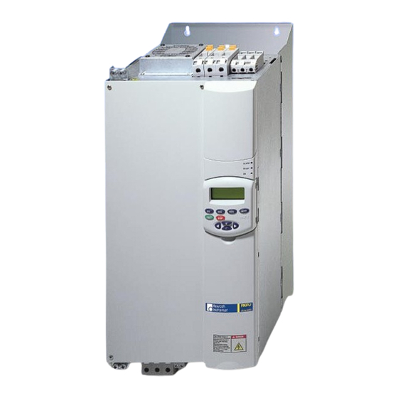
Rexroth Indramat REFUdrive 500 RD51 Operating Instructions Manual (96 pages)
Drive control devices, VFC (voltage-frequency-control)
Brand:
Rexroth Indramat
| Category:
Control Unit
| Size: 5 MB
Table of Contents
List of
3
Table of Contents
3
Safety
7
Safety Information and Instructions in the Technical Documentation for Refudrive500
7
Definition of the Terminology Used
7
Definition of the Symbols Used
8
Precautionary Measures When Handling Components Which Can be Destroyed by Electrostatic Discharge (ESD)
8
Description
11
The REFU Drive 500 Drive Converters
11
Handling
11
Electromagnetic Compatibility
11
Technical Features
11
Rating Plate
12
Technical Data
13
Technical Data for Pulse Frequency F = 4 Khz
13
Technical Data for Pulse Frequency F = 4 Khz
14
P = 8 Khz
15
Technical Data for Pulse Frequency F
15
Khz (* for 110 Kw F P = 6 Khz)
15
Technical Data for Pulse Frequency F = 10 and 12 Khz
17
Circuit Principle
18
Electronic Section
18
Converter Power Section
19
Type Code
21
Mechanically Installation
23
Storage and Installation Location
23
Storage
23
Minimum Requirements Regarding the Installation Location
23
Installation Altitudes Exceeding 1000 Meter above Sea Level
23
Mounting Units Sizes a to E
24
Mounting Example
24
Dimension Drawings Front View, Sizes a to E
25
Dimension Drawing Side View, Sizes a to E
26
Mounting Liquid-Cooled Converters, Sizes G and H with Integrated Heat Exchanger
27
Dimension Drawing with Integrated Heat Exchanger, Size G
27
Dimension Drawing with Heat Exchanger, Size H
28
Mounting Liquid-Cooled Converters, Sizes G and H with External Heat Exchanger
28
Dimension Drawing of the Drive Converter and Line Filter Without Heat Exchanger, Size G
29
Dimension Drawing of the Drive Converter and Filter Without Heatexchanger, Size H
30
Dimension Drawing of the External Heat Exchanger for Cabinet Mounting
31
Dimension Drawings of the External Heat Exchanger for Wall Mounting
31
Working on the Cooling-Medium Circuit
31
Mounting Extension Hoses for External Heat Exchangers
31
Servicing the Cooling Medium Circuit
32
Electrical Installation
33
EMC-Compatible Drive Design
33
Warning Notes and Informations
34
Conductor Cross-Section
36
Power Terminals RD51, Size Class a - E
38
Terminal Layout Diagram, Size Class a
38
Terminal Layout Diagram, Sizes B - E
39
Description of the Power Terminals, Size Class a to E
40
Power Terminals RD51, Sizes G and H
41
Terminal Layout Diagram, Size G
41
Terminal Layout Diagram, Size H
42
Description of the Power Terminals, Sizes G and H
43
Connection Diagrams
44
Control Terminals
45
Terminal Layout Diagram SR17000
45
Description of the Control Terminals
45
Incremental Encoder Connection
47
Service Interface RS232 (X11)
48
Standard Interfaces RS485 (X12)
49
Operator Control and Parameterization
51
Operating Possibilities
51
Using the Operator Panel
51
Operating Using the Operator Panel
51
Monitoring Using the Operator Panel (Monitor)
52
Parameterizing Using the Operator Panel
52
Copy Function
53
Fault Acknowledgment
53
Monitoring
54
Monitor Stucture
54
Monitor Functions
55
Operating Display
55
Alarm Display
55
Fault Display
56
LED Display
56
Basic Parameterization
57
Parameterizing
57
Structure of the Basic Parameterization
57
Overview
58
Password Level
60
Quick-Setup
60
Guided Parameterization
62
Device Control / Setpoints
62
Standard Terminal Assignment
64
Functions
66
Drive Converter Settings
70
Serial Communications
71
Diagnostica / Drive Converter Data
72
Optiones
73
Numerical List
73
Start-Up
75
Steps to Prepare for Commissioning
75
Procedure When First Commissioning
75
Motor Optimization / Motor Evaluation
77
Motor Running under No-Load Conditions
77
Running-Up/Accelerating under Load
77
General Information
77
Troubleshooting
79
Self Test - Error Messages
79
Alarms
79
Faults
79
Fault Acknowledgment
79
7.4 List of the Alarm- and Fault Messages
80
List of the Alarm- and Fault Messages
80
Troubleshooting
81
Alarm- and Fault Messages - Cause and Remedy/Comments
81
Brake Resistor
81
DC Link Voltage too High
81
DC Link Voltage too Low
81
Device Overtemperature
81
External
81
Main Contactor
81
Inverter
82
New EEPROM
82
Power Section
82
Pre-Charging
82
EEPROM Data
83
Ground Fault
83
Internal WS Comm
83
NTC Power Section
83
Overspeed
83
Power Supply
83
SI1 Timeout
83
SI2 Function
83
Analog Input 1: I < 4 Ma
84
BW Overload
84
Motor Oertemperature
84
SI2 Timeout
84
SR-Release
84
Motor Overload
85
Overcurrent
85
Safety off
85
Start Protection on
85
SI4 Function
86
SI4 Timeout
86
SR <==> WS New
86
Start Protection on
86
Switched Power Supply
86
Index
87
Technical Data for Pulse Frequency F P = 10 and 12 Khz
89
Kundenbetreuungsstellen - Sales & Service Facilities
91
Advertisement
Advertisement
Related Products
Rexroth Indramat Mannesmann Rexroth CLM-01.3-M
Rexroth Indramat Categories
Controller
Control Unit
Amplifier
Industrial Electrical
More Rexroth Indramat Manuals
Login
Sign In
OR
Sign in with Facebook
Sign in with Google
Upload manual
Upload from disk
Upload from URL