Sign In
Upload
Manuals
Brands
Renesas Manuals
Microcontrollers
FPB-RA6E2
Renesas FPB-RA6E2 Manuals
Manuals and User Guides for Renesas FPB-RA6E2. We have
1
Renesas FPB-RA6E2 manual available for free PDF download: User Manual
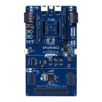
Renesas FPB-RA6E2 User Manual (31 pages)
Fast Prototyping Board for RA6E2 Microcontroller
Brand:
Renesas
| Category:
Microcontrollers
| Size: 1 MB
Table of Contents
Table of Contents
5
Glossary
7
Table 1. List of Abbreviations and Acronyms
7
Board Overview
8
Figure 1. FPB-RA6E2 Board Top Side
9
Figure 2. FPB-RA6E2 Board Bottom Side
9
Assumptions and Advisory Notes
10
Box Contents
11
Ordering Information
11
Figure 3. FPB-RA6E2 Board
11
Hardware Architecture and Default Configuration
12
Board Architecture
12
System Block Diagram
12
Figure 4. FPB-RA6E2 Board Block Diagram
12
Table 2. Kit Architecture
12
Jumper Settings
13
Copper Jumpers
13
Traditional Pin Header Jumpers
13
Default Jumper Configuration
13
Figure 5. Copper Jumpers
13
Table 3. Default Jumper Settings
13
System Control and Ecosystem Access
14
Power
14
Power Supply Options
15
Figure 6. Power Supply Options
15
Power Supply Considerations
16
Power-Up Behavior
16
Debug and Trace
16
On-Board Debug
16
Figure 7. FPB-RA6E2 Debug Interface
16
Table 4. Debug USB Connector
16
Debugger Settings in E 2 Studio
17
Figure 8. E 2 Studio Debugger Settings
17
Table 5. Debug Link Settings
17
Ecosystem
18
Digilent Pmod™ Connectors
18
Table 6. Pmod 1 Connector
18
Figure 9. Pmod 1 Connector
19
Figure 10. Pmod 1 Solder Bridge and Trace Cut Jumpers
19
Table 7. Pmod 2 Connector
19
Arduino™ Connector
20
Figure 11. Pmod 2 Connector
20
Figure 12. Pmod 2 Solder Bridge and Trace Cut Jumpers
20
Table 8. Arduino uno Connections
20
Miscellaneous
22
User and Power Leds
22
Figure 13. Arduino uno Connectors
22
Figure 14. User Leds
22
Table 9. FPB-RA6E2 Board LED Functions
22
User and Reset Switches
23
Figure 15. Power LED
23
Figure 16. Debug LED
23
Figure 17. Reset (S2) and User Switch (S1)
23
Table 10. FPB-RA6E2 Board Switches
23
MCU Boot Mode
24
MCU Clocks
24
MCU Native Pin Access
24
Figure 18. Boot Mode Jumper (J7)
24
Figure 19. Native Pin Access J3 and J4
24
Breakout Pin Headers
25
MCU Current Measurement
25
Figure 20. RA +3.3 V Current Measurement Circuit
25
Figure 21. RA MCU +3.3 V Current Measurement Point (J9) and R94
25
Recommended Parts
26
Table 11. Part Numbers
26
R20UT5161EG0100 Rev
27
Certifications
27
EMC/EMI Standards
27
Material Selection, Waste, Recycling and Disposal Standards
27
Safety Standards
27
Design and Manufacturing Information
28
Website and Support
28
Table 12. FPB-RA6E2 Board Design Package Contents
28
Revision History
29
Advertisement
Advertisement
Related Products
Renesas FPB-RA2E2
Renesas FG4-768K Series
Renesas FG4-1M Series
Renesas FL4-1.5M Series
Renesas FL4-2M Series
Renesas FJ4-512K Series
Renesas FJ4-768K Series
Renesas FJ4-1M Series
Renesas FJ4-1.5M Series
Renesas FK4-1.5M Series
Renesas Categories
Computer Hardware
Motherboard
Microcontrollers
Adapter
Switch
More Renesas Manuals
Login
Sign In
OR
Sign in with Facebook
Sign in with Google
Upload manual
Upload from disk
Upload from URL