Sign In
Upload
Manuals
Brands
Renesas Manuals
Computer Hardware
EK-RA8D1
Renesas EK-RA8D1 Manuals
Manuals and User Guides for Renesas EK-RA8D1. We have
2
Renesas EK-RA8D1 manuals available for free PDF download: User Manual, Quick Start Manual
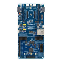
Renesas EK-RA8D1 User Manual (50 pages)
Evaluation Kit for RA8D1 Microcontroller Group
Brand:
Renesas
| Category:
Motherboard
| Size: 11 MB
Table of Contents
Corporate Headquarters
2
Contact Information
2
Table of Contents
5
Kit Overview
9
Figure 1. EK-RA8D1 Board Top Side
10
Figure 2. EK-RA8D1 Board Bottom Side
11
Assumptions and Advisory Notes
12
Kit Contents
13
Figure 3. EK-RA8D1 Kit Contents
13
Ordering Information
14
Hardware Architecture and Default Configuration
14
Kit Architecture
14
Table 1. Kit Architecture
14
Figure 4. EK-RA8D1 Board Functional Area Definitions
15
System Block Diagram
16
Figure 5. EK-RA8D1 Board Block Diagram
16
Jumper Configuration
17
Copper Jumpers
17
Traditional Pin Header Jumpers
17
Default Jumper Configuration
17
Figure 6. Copper Jumpers
17
Table 2. Default Jumper Configuration
17
Default Switch Configuration
19
Table 3. Default Switch Configuration (SW1)
19
Table 4. Permitted Switch Configuration (SW1)
19
System Control and Ecosystem Access Area
20
Figure 7. System Control and Ecosystem Access Area
20
Power
21
Power Supply Options
21
Figure 8. Power Supply Options
21
Power Supply Considerations
22
Power-Up Behavior
22
Debug and Trace
22
Figure 9. Test Point Location
22
Table 5. Debug Modes
22
Debug On-Board
23
Table 6. Jumper Connection Summary for Different Debug Modes
23
Table 7. Debug USB Port Assignments
23
Table 8. Debug On-Board Jumper Configuration
23
Debug in
24
Figure 10. EK-RA8D1 Debug Interface
24
Table 9. Debug in Mode Jumper Configuration
24
Table 10. JTAG/SWD/ETM Debug Port Assignments
24
Debug out
25
Ecosystem
25
Table 11. JTAG/SWO/SWD Debug Port Assignments
25
Table 12. Debug out Jumper Configuration
25
Seeed Grove ® Connectors
26
Sparkfun Qwiic ® Connector
26
Figure 11. Seeed Grove and Sparkfun Qwiic ® Connectors
26
Table 13. Grove 1 Port Assignments
26
Table 14. Grove 2 Port Assignments
26
Table 15. Qwiic Port Assignments
26
Digilent Pmod™ Connectors
27
Table 16. Pmod 1 Port Assignments
27
Arduino™ Connector
28
Figure 12. Pmod 1 Connector
28
Figure 13. Pmod 2 Connector
28
Table 17. Pmod 2 Port Assignments
28
Table 18. Arduino uno Port Assignments
28
Figure 14. Arduino uno Connectors
29
Mikroelektronika™ Mikrobus Connector
30
Connectivity
30
USB Full Speed
30
Figure 15. Mikrobus Connection
30
Table 19. Mikrobus Assignments
30
I3C
31
Miscellaneous
31
User and Power Leds
31
Figure 16. USB Full Speed Connector
31
Table 20. USB Full Speed Port Assignments
31
Table 21. I 2 C/I3C Pullup Configuration
31
Table 22. EK-RA8D1 Board LED Functions
31
User and Reset Switches
32
Figure 17. User Leds
32
Figure 18. Power LED
32
Figure 19. Reset and User Switches
32
Table 23. EK-RA8D1 Board Switches
32
MCU Boot Mode
33
Special Feature Access Area
33
Ethernet
33
Figure 20. Boot Mode
33
Figure 21. Special Feature Access Area
33
USB High Speed
34
Figure 22. Ethernet Connector
34
Table 24. Ethernet Port Assignments
34
Table 25. Ethernet Components
34
Octo-SPI Flash
35
Figure 23. USB High Speed Connector
35
Figure 24. Octo-SPI Flash
35
Table 26. USB High Speed Port Assignments
35
Table 27. Octo-SPI Flash Assignments
35
Sdram
36
Table 28. SDRAM Assignments
36
Parallel Graphics Expansion Port
37
Figure 25. SDRAM
37
Table 29. Parallel Graphics Expansion Port Assignments
37
Figure 26. Parallel Graphics Expansion Port
38
MCU Native Pin Access Area
39
Breakout Pin Headers
39
MCU and USB Current Measurement
39
Figure 27. Native Pin Access Area
39
Figure 28. RA USB Current Measurement Circuit
40
Figure 29. RA +3.3 V Current Measurement Circuit
40
Figure 30. RA MCU and USB Current Measurement
40
Expansion Boards
41
MIPI Graphics Expansion Board
41
Connecting the Graphics Expansion Board to the EK-RA8D1 Board
41
Figure 31. EK-RA8D1 Board Connected with MIPI Graphics Expansion Board
42
Signal Assignments
43
Camera Expansion Board
43
Connecting the Camera Expansion Board to the EK-RA8D1 Board
43
Table 30. MIPI Graphics Expansion Port Assignments
43
Figure 32. EK-RA8D1 Board Connected with Camera Expansion Board
44
Signal Assignments
45
Table 31. Camera Expansion Port Assignments
45
Certifications
46
EMC/EMI Standards
46
Material Selection, Waste, Recycling and Disposal Standards
46
Safety Standards
46
Design and Manufacturing Information
47
Website and Support
47
Table 32. EK-RA8D1 Board Design Package Contents
47
Table 33. MIPI Graphics Expansion Board Design Package Contents
47
Revision History
48
Advertisement
Renesas EK-RA8D1 Quick Start Manual (42 pages)
Brand:
Renesas
| Category:
Computer Hardware
| Size: 3 MB
Table of Contents
Table of Contents
5
1 Introduction
8
Assumptions and Advisory Notes
8
2 Kit Contents
9
Figure 1. EK-RA8D1 Kit Contents
9
3 Kit Assembly
10
Nylon Screw Assembly
10
Figure 2. Kit Assembly
10
Camera Expansion Board
11
Figure 3. Correct Connection for Camera Expansion Board
11
Figure 4. Incorrect Connection for Camera Expansion Board
11
Figure 5. Incorrect Connection for Camera Expansion Board
11
4 Overview of the Quick Start Example Project
12
Quick Start Example Project Flow
12
Figure 6. Quick Start Example Project Flow
12
5 Running the Quick Start Example Project on Display
13
Connecting and Powering up the EK-RA8D1 Board
13
Figure 7. Connecting the EK-RA8D1 Board to the Host PC Via USB Debug Port
13
Running the Quick Start Example Project
14
Figure 8. USB Serial (UART) Device in Windows Device Manager
14
Figure 9. Selecting the Serial Port on Tera Term
15
Figure 10. Select 115200 on the Speed Pulldown
15
Figure 11. Various Interactive Connectivity and HMI Demos
16
Figure 12. Unsuccessful Configuration
16
Common Application Details
17
Figure 13. Splash Screen
17
Figure 14. Main Screen
17
Figure 15. Main Menu
18
Figure 16. Kit Information
18
Figure 17. Getting Started
19
Figure 18. User LED Control
19
Connectivity Application Details
20
Currency Converter
20
Figure 19. Currency Conversion Screen
20
World Time Zones
21
World Weather
21
Figure 20. World Time Zone Screen
21
Figure 21. World Weather
21
AI Application Details
22
Face Detection
22
Figure 22. Invalid Configuration Example
22
Figure 23. Face Detection
22
Image Classification
23
6 Running the Quick Start Example Project on Console
23
Figure 24. Image Classification Example
23
Figure 25. Welcome and Main Menu
23
Connectivity Application API Keys
24
Figure 26. Kit Information
24
Figure 27. Interactive AI, Connectivity & HMI Demos
24
Currency Converter Refresh
25
Figure 28. Welcome and Main Menu
25
World Time Zones Refresh
26
Figure 29. Currency Converter Refresh
26
Figure 30. Entering Currency API Keys for the First Time
26
World Weather Refresh
27
Figure 31. World Time Zones Refresh
27
Figure 32. Entering Time Zone API Keys for the First Time
27
API Keys Help and Management
28
Figure 33. World Weather Refresh
28
Figure 34. Entering Weather API Keys for the First Time
28
Next Steps
29
Figure 35. API Keys Help and Management
29
Figure 36. Next Steps
29
7 Customizing the Quick Start Example Project
30
Downloading and Installing Software and Development Tools
30
Downloading and Importing the Quick Start Example Project
30
Figure 37. Creating a New Workspace
30
Figure 38. Launching the Workspace
31
Figure 39. Importing the Project
31
Figure 40. Importing Existing Projects into the Workspace
32
Figure 41. Clicking Next to Import Existing Projects into the Workspace
32
Figure 42. Selecting the Root Directory
33
Figure 43. Finishing Importing the Quick Start Example Project
33
Modifying, Generating, and Building the Quick Start Example Project
34
Figure 44. Opening the Configurator
34
Figure 45. Open Perspective
34
Figure 46. Modifying the Configuration Settings
35
Figure 47. Saving the Configuration Changes
35
Setting up Debug Connection between the EK-RA8D1 Board and Host PC
36
Figure 48. Building the Project
36
Figure 49. Successful Build Output
36
Figure 50. Connecting the EK-RA8D1 Board to the Host PC Via USB Debug Port
36
Downloading and Running the Modified Quick Start Example Project
37
Figure 51. Selecting the Debug Option
37
Figure 52. Selecting the Debug Image
37
Firewall Dialog
38
Figure 53. Opening the Debug Perspective
38
Figure 54. Executing the Project
38
8 Next Steps
39
9 Website and Support
39
Revision History
40
Advertisement
Related Products
Renesas EK-RA4L1
Renesas EDK3687
Renesas Emulator System E8
Renesas SuperH E10A
Renesas E200F
Renesas E2 Lite
Renesas E8000
Renesas E2 Emulator
Renesas E2 Emulator Lite
Renesas E30A
Renesas Categories
Computer Hardware
Motherboard
Microcontrollers
Adapter
Switch
More Renesas Manuals
Login
Sign In
OR
Sign in with Facebook
Sign in with Google
Upload manual
Upload from disk
Upload from URL