Sign In
Upload
Manuals
Brands
Renesas Manuals
Motherboard
EK-RA4M3
Renesas EK-RA4M3 Manuals
Manuals and User Guides for Renesas EK-RA4M3. We have
2
Renesas EK-RA4M3 manuals available for free PDF download: User Manual, Quick Start Manual
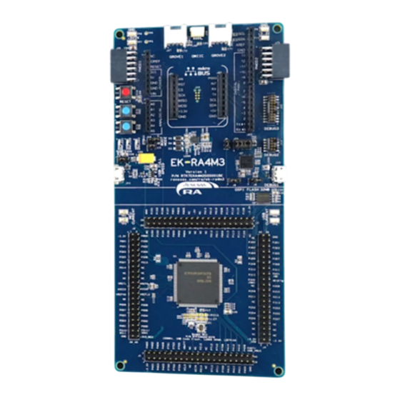
Renesas EK-RA4M3 User Manual (35 pages)
Evaluation Kit for RA4M3 Microcontroller Group
Brand:
Renesas
| Category:
Motherboard
| Size: 4 MB
Table of Contents
Table of Contents
5
Kit Overview
8
Figure 1. EK-RA4M3 Board Top Side
9
Assumptions and Advisory Notes
10
Figure 2. EK-RA4M3 Board Bottom Side
10
Kit Contents
11
Kit Ordering Information
11
Figure 3. EK-RA4M3 Kit Contents
11
Hardware Architecture and Default Configuration
12
Kit Architecture
12
Figure 4. EK-RA4M3 Board Functional Area Definitions
12
System Block Diagram
13
Figure 5. EK-RA4M3 Board Block Diagram
13
Jumper Settings
14
Copper Jumpers
14
Traditional Pin Header Jumpers
14
Default Jumper Configuration
14
Figure 6. Copper Jumpers
14
Table 1. Default Jumper Settings
14
System Control and Ecosystem Access Area
16
Figure 7. System Control and Ecosystem Access Area
16
Power
17
Power Supply Options
17
Power Supply Considerations
17
Power-Up Behavior
17
Figure 8. Power Supply Options
17
Debug and Trace
18
Debug On-Board
18
Table 2. Debug Modes
18
Table 3. Jumper Connection Summary for Different Debug Modes
18
Table 4. Debug USB Connector
18
Debug in
19
Figure 9. EK-RA4M3 Debug Interface
19
Table 5. Debug On-Board Jumper Configuration
19
Table 6. Debug in Mode Jumper Configuration
19
Debug out
20
Table 7. JTAG/SWD/TRACE Connector
20
Table 8. JTAG/SWD Connector
20
Ecosystem
21
Seeed Grove ® Connectors
21
Figure 10. Seeed Grove and Qwiic Connectors
21
Table 9. Debug out Jumper Configuration
21
Table 10. Grove 1 Connector
21
Table 11. Grove 2 Connector
21
Sparkfun Qwiic Connector
22
Digilent Pmod™ Connectors
22
Figure 11. Pmod 1
22
Table 12. Qwiic Connector
22
Table 13. Pmod 1 Connector
22
Figure 12. Pmod 1 Trace Cut Jumpers
23
Table 14. Pmod 2 Connector
23
Arduino™ Connector
24
Figure 13. Pmod 2
24
Table 15. Arduino uno Connections
24
Mikroelektronika™ Mikrobus Connector
25
Figure 14. Arduino uno Connectors
25
Table 16. Mikrobus Connections
25
Connectivity
26
USB Full Speed
26
Figure 15. Mikrobus Connection
26
Figure 16. USB Full Speed Connector
26
Table 17. USB Full Speed Connector
26
Miscellaneous
27
User and Power Leds
27
User and Reset Switches
27
Figure 17. User Leds
27
Figure 18. Power LED
27
Table 18. EK-RA4M3 Board LED Functions
27
Table 19. EK-RA4M3 Board Switches
27
MCU Boot Mode
28
Special Feature Access Area
28
Quad-SPI Flash
28
Figure 19. Reset and User Switches
28
Figure 20. Boot Mode
28
Figure 21. Special Feature Access Area
28
Table 20. Quad-SPI Flash Port Assignments
28
MCU Native Pin Access Area
29
Figure 22. Quad-SPI Flash
29
Figure 23. Native Pin Access Area
29
Breakout Pin Headers
30
MCU and USB Current Measurement
30
Figure 24. RA USB Current Measurement Circuit
30
Figure 25. RA +3.3 V Current Measurement Circuit
30
Figure 26. RA MCU Current Measurement
30
Certifications
31
EMC/EMI Standards
31
Material Selection, Waste, Recycling and Disposal Standards
31
Safety Standards
31
Design and Manufacturing Information
32
Website and Support
32
Table 21. EK-RA4M3 Board Design Package Contents
32
Revision History
33
Advertisement
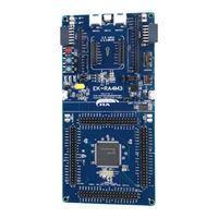
Renesas EK-RA4M3 Quick Start Manual (28 pages)
Evaluation Kit for RA4M3 Microcontroller Group
Brand:
Renesas
| Category:
Motherboard
| Size: 2 MB
Table of Contents
Table of Contents
5
Ek-Ra4M3
7
Figure 1. EK-RA4M3 Kit Contents
7
1 Introduction
7
Assumptions and Advisory Notes
7
2 Kit Contents
7
Figure 2. Quick Start Example Project Flow
8
3 Overview of the Quick Start Example Project
8
Quick Start Example Project Flow
8
Connecting and Powering up the EK-RA4M3 Board
9
Figure 3. Connecting the EK-RA4M3 Board to the Host PC Via USB Full Speed Port
9
4 Running the Quick Start Example Project
9
Figure 4. USB Serial Device in Windows Device Manager
10
Running the Quick Start Example Project
10
Figure 5. Selecting the Serial Port on Tera Term
11
Figure 6. Select 115200 on the Speed Pulldown
11
Figure 7. Welcome and Main Menu
12
Figure 8. Kit Information
12
Figure 9. Quad-SPI Block Write Size
12
Renesas RA Family
12
Figure 10. Quad-SPI Speed Measurement
13
Figure 11. Next Steps
13
5 Customizing the Quick Start Example Project
14
Downloading and Importing the Quick Start Example Project
14
Downloading and Installing Software and Development Tools
14
Figure 12. Creating a New Workspace
14
Figure 13. Launching the Workspace
15
Figure 14. Importing the Project
15
Figure 15. Importing Existing Projects into the Workspace
16
Figure 16. Selecting the Root Directory
17
Figure 17. Finishing Importing the Quick Start Example Project
18
Figure 18. Opening the Configurator
19
Modifying, Generating, and Building the Quick Start Example Project
19
Figure 19. Modifying the Configuration Settings
20
Figure 20. Saving the Configuration Changes
21
Figure 21. Building the Project
21
Figure 22. Successful Build Output
21
Figure 23. Connecting the EK-RA4M3 Board to the Host PC Via USB Debug Port
22
Setting up Debug Connection between the EK-RA4M3 Board and Host PC
22
Downloading and Running the Modified Quick Start Example Project
23
Figure 24. Selecting the Debug Option
23
Figure 25. Selecting the Debug Image
23
Figure 26. Opening the Debug Perspective
24
Figure 27. Executing the Project
24
Firewall Dialogue
24
6 Next Steps
25
7 Website and Support
25
Revision History
26
Advertisement
Related Products
Renesas EK-RA4M1
Renesas EK-RA4W1
Renesas EK-RA4M1 v1
Renesas EK-RA4M2 v1
Renesas EK-RA4M2
Renesas EK-RA4E2
Renesas EK-RA4L1 v1
Renesas EK-RA6M1
Renesas EK-RA6M3G v1
Renesas EK-RA2A1 v1
Renesas Categories
Computer Hardware
Motherboard
Microcontrollers
Adapter
Switch
More Renesas Manuals
Login
Sign In
OR
Sign in with Facebook
Sign in with Google
Upload manual
Upload from disk
Upload from URL