Sign In
Upload
Manuals
Brands
Reliance electric Manuals
Controller
HR2000 Series
Reliance electric HR2000 Series Manuals
Manuals and User Guides for Reliance electric HR2000 Series. We have
1
Reliance electric HR2000 Series manual available for free PDF download: Installation, Operation And Maintenance Instructions
Reliance electric
HR2000 Series
Installation, Operation And Maintenance Instructions
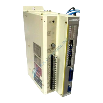
Reliance electric HR2000 Series Installation, Operation And Maintenance Instructions (79 pages)
Three-Phase Input High Performance Controller and Motor
Brand:
Reliance electric
| Category:
Controller
| Size: 1 MB
Table of Contents
Table of Contents
3
1 : Receive and Accept the Drive
7
Identify the Drive
7
Receive and Accept the Shipment
8
File a Return Request
8
Store the Drive until Installation
8
2 : Know the Drive
9
Terminology Used in this Manual
9
Definitions and Abbreviations
9
Dangers, Warnings, and Cautions
9
Drive Components
9
Controller Leds
9
Controller Regulator Pots
10
Controller Regulator Switches
10
Controller Regulator Jumpers
10
Figure 2-1. Typical Controller Faceplate Components
10
Customer Interlocks, Inputs, and Output Signals
11
Controller Features
11
Standard Features
11
Optional Features
11
Motor Features
11
Drive Specifications
12
Ratings
12
Fuse Data
12
Torque and Inertia Data
12
Service Conditions
12
Application Data
12
Adjustments
12
Product Publications
12
Table 2-1. Controller Ratings
12
Figure 2-2. 7.5 HP and 15 HP Torque and Inertia Data
13
Figure 2-3. 2500 RPM and 3000 RPM Torque and Inertia Data
14
Table 2-2. Servo Motor Engineering Data
15
Figure 2-4. 10 HP Torque and Inertia Data
15
Figure 2-5. Servo Motor Torque Data
16
3 : Install the Drive
17
Plan and Perform the Installation
17
Select the Controller Location
17
Install the Controller
17
Figure 3-1. Chassis Controller Dimensions and Weights
18
Install the Motor
19
Install a Transformer (if Needed)
19
Install an Input Disconnect
19
Suppress Electrical Noise
19
Figure 3-2. Motor Mounting Dimensions
20
Figure 3-2A. S-6200 and S-6300 Motor Dimesions
21
Figure 3-2B. S-8350 and S-8500 Motor Dimesions
22
Review the 2CN Connector Pin Functions before Wiring
23
12-Volt Control Power Supply
23
Analog Input Signals
23
Figure 3-3. Speed/Torque Reference Circuitry
23
Analog Output Signals
24
Figure 3-4. External Current Limit Pot Circuitry
24
Figure 3-5. Typical Circuitry for Monitoring Speed/Torque
24
Logic Input Signals
25
Figure 3-6. Typical Optically Isolated Input
25
Logic Output Signals
26
Figure 3-7. Typical Optically Isolated Output
26
Signal Inputs
27
Figure 3-8. Typical Position Reference Circuits
27
Signal Outputs
28
Figure 3-9. Typical Signal Output Circuitry and Pulse Relationship
28
Figure 3-10. Internal Input Power Supply Connections
29
Wire the Drive
29
Figure 3-11. Location of Typical Control Wiring and Startup Components
30
Figure 3-11A. Blower Motor Connection Diagram
31
Provide Appropriate Grounding
31
Make Control and Signal Wiring Connections
32
Table 3-1. Drive Short Circuit Protection Requirements
32
Figure 3-12. Typical Connection Diagram
33
Figure 3-13. 2CN Connector Pin Configuration
34
Table 3-2. 2CN Connector Pin Details
35
Figure 3-14. 3CN and Encoder (Motor MS) Connector Pin Configurations
36
Table 3-3. 3CN Connector Pin Details (Grouped by Required Twisted Pair)
36
Set Regulator Dip Switches
37
Table 3-4. Dip Switch Descriptions
37
4 Start and Adjust the Controller
38
Table 4-1. Default Values of EEPROM Version J or Later
39
Table 4-2. Motor/Encoder Characteristics for Initialization
39
Initialize the Regulator
39
Figure 4-1. INIT0 1SW DIP Switch Settings
40
Figure 4-2. INIT2 1SW DIP Switch Settings
41
Figure 4-3. INIT3 1SW DIP Switch Settings
41
Review the Controller Regulator Jumpers
42
Figure 4-4. Typical Notch Filter Wave Form
43
Figure 4-5. Curves Showing Ranges of Regulator Pots
43
Start the Controller
44
Figure 4-6. Controller Switch and Pot Settings for Procedure 1 and Speed Mode
45
Perform Startup Procedure 2 with Motor Coupled
47
Figure 4-7. Speed Feedback Signals
49
Figure 4-8. Controller Switch Settings for Torque Mode
50
Perform Startup in Torque Regulator Mode
50
Perform Startup in Position Regulator Mode
51
5 : Understand How the Controller Operates
53
Fundamentals of the HR2000 Controller and the Motor
53
Figure 5-1. Pulse Output, One Revolution for a Two-Pole Machine
54
Fundamentals of Controller's Operator Controls
54
Figure 5-2. Adding Resistors to Obtain Neutral
55
Figure 5-3. Typical Functional Block Diagram
56
6 Service the Motor
57
Reassemble the Motor
58
7 Service the Controller
59
Table 7-1. Red LED Functions and Possible Causes for Fault
60
Understand Controller Status Indicators
61
Identify Fault Symptoms and Correct Using Flow Charts
62
Figure 7-1. Motor will Not Run
63
Figure 7-2. Motor Runs at Uncontrolled Speed
64
Figure 7-3. Motor Rotation Is Unstable
65
Figure 7-4. Acceleration/Deceleration Is Not Smooth
66
Figure 7-5. Heavy Vibration Results When Motor Stops
67
Figure 7-6. Polarity Check at Diode
68
Figure 7-7. Transistor Terminals
68
Table 7-2. Transistor Terminals from Which to Take Readings
68
Power Unit Checks
68
Figure 7-8. Typical Transistor Wiring
69
Table 7-3. Transistor Resistance Readings
69
Table 7-4. Replacement Parts List
70
Table 7-5. Modification Kits
71
Figure 7-9. Typical Wiring Diagram
72
Figure 7-10. Typical Functional Block Diagram
73
Figure 7-11. Typical Regulator Board Component Layout
74
Advertisement
Advertisement
Related Products
Reliance electric P21M301
Reliance electric P21M302
Reliance electric P21M303
Reliance electric P21M304
Reliance electric P21M305
Reliance electric P21M306
Reliance electric P21M307
Reliance electric P21M308
Reliance electric SP500
Reliance electric VS 3RA2008
Reliance electric Categories
DC Drives
Control Unit
Controller
Media Converter
Circuit breakers
More Reliance electric Manuals
Login
Sign In
OR
Sign in with Facebook
Sign in with Google
Upload manual
Upload from disk
Upload from URL