Sign In
Upload
Manuals
Brands
REITZ Manuals
Fan
Design KXE
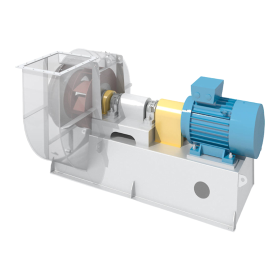
REITZ Design KXE Radial Fan Manuals
Manuals and User Guides for REITZ Design KXE Radial Fan. We have
1
REITZ Design KXE Radial Fan manual available for free PDF download: Original Instructions Manual
REITZ Design KXE Original Instructions Manual (128 pages)
Single Stage Radial Fan
Brand:
REITZ
| Category:
Fan
| Size: 1 MB
Table of Contents
Table of Contents
3
1 Preface
6
2 Introduction
7
Legal Notices
8
EC Declarations
9
Utilisation of the Operating Manual
9
Regulations and Standards
10
3 Fundamental Safety Instructions
11
Symbols and Warning Information
11
Authorised Personnel
13
Qualified Persons
13
Electrical Specialists
13
Personal Protective Equipment
14
Overview of Hazards
16
Obligations of the Operating Company
18
Intermediate Storage
18
Measures in the Event of a Power Failure
18
Risk of Slipping, Tripping or Tumbling
19
4 Product Description
20
Intended Use
21
Product Identification and Labelling
24
Fig. 4-1 Labelling and Identification
24
Technical Data
25
Fig. 4-2 Nameplate (Example)
25
Fig. 4-3 Nameplate in Accordance with Erp Directive (Example)
25
Fig. 4-4 Nameplate in Accordance with ATEX (Example)
26
Fig. 4-5 Vessel Plate (Example)
26
Drive
27
Motor
27
Additional Components
27
Variable Speed Control (Optional)
27
5 Accessories
28
Anti-Vibration Mounts
28
Flexible Connections
28
Monitoring Devices
28
Additional Accessories
28
6 Transport
29
Transport with a Crane
29
Fig. 6-1 Slinging Points
29
Fig. 6-2 Transport Bracing
29
Transport with a Truck
30
Packaging
30
Transport Damage
31
Intermediate Storage
32
7 Installation
33
Preparing for Installation
34
Mounting and Alignment
35
Assembling the Fan
36
Fig. 7-1 Spatial Requirement at the Assembly Site (Fan Shown as an Example)
36
Procedure
37
Screw Connections
38
Securing the Fan
39
Anti-Vibration Mount
40
Fig. 7-2 Securing of Anti-Vibration Mounts
40
Spring Phonolators (Spring Type Anti-Vibration Mounts)
41
Stone Bolts
41
Fig. 7-3 Securing of Spring Phonolators
41
Fig. 7-4 Securing of Stone Bolts
41
Insulation of the Fan
42
8 Measures Prior to Commissioning
43
Aligning the Coupling
44
Fig. 8-1 Coupling Offsets
44
Checking the Impeller Gap
47
Fig. 8-2 Impeller Gap
47
Fig. 8-3 Impeller Gap for Unshrouded Impeller
48
Connecting the Duct Work
49
Fitting the Flexible Connections
51
Fig. 8-4 Fitted Flexible Connection
51
Fig. 8-5 Chute (Standard Configuration) in Direction of Flow
51
Fig. 8-6 Chute (Overlapping Configuration) in Direction of Flow
51
Activating the Re-Lubrication Devices
53
Fig. 8-7 Re-Lubrication Device on the Bearing (Example)
53
Fig. 8-8 Cartridge for Re-Lubrication Device on the Shaft Seal (Example)
53
Bearings
54
Shaft Seal
56
Connecting the Shaft Seal
57
Fig. 8-9 Shaft Seal with Connection for Barrier Gas
57
Fig. 8-10 Instrument Panel for Shaft Seals with Barrier Gas Supply
58
Electrical Connection
59
Fig. 8-11 Drawing of Potential Equalisation System
60
Fig. 8-12 Earthing Clamp
61
Connecting the Monitoring Devices
62
Monitoring Devices Limit Values
63
Vibrations
64
Temperatures
65
Connecting the Cooler Fan
66
Fig. 8-13 Cooler Fan
66
Checking the Lubricant
67
Fig. 8-14 Anti-Corrosion Oil Information Plate
69
Connecting the External Oil Supply System
70
Fig. 8-15 External Oil Supply System
70
Checking the Final Installation Condition
71
9 Start-Up
73
Switching on the Fan
74
Checking the Sense of Rotation
74
Fig. 9-1 Checking the Sense of Rotation
74
Powering up the Fan
75
Direct Connection
77
Star-Delta Starting
77
Variable Speed Control
77
Switching off the Fan
80
10 Operation
81
Regulation Via Variable Speed Control
83
Emergency Shutdown
83
Exceeding Limit Values
83
Minimum Duration of Operation
84
Minimum Speeds
85
Maximum Speeds
86
11 Fault and Rectification
87
12 Inspecting the Fan
91
Weekly Inspections
92
Monthly Inspections
93
Annual Inspections
94
13 Maintenance
95
Lubricants
97
Bearings
99
Fig. 13-1 Single Bearing
99
Fig. 13-2 Multiple Bearing Block
99
Fig. 13-3 Borehole for Exuding of Grease (Example)
100
Grease-Lubricated Single Bearing
101
Grease-Lubricated Multiple Bearing Block
102
Oil-Lubricated Single Bearing
104
Oil-Lubricated Multiple Bearing Block
105
Oil Change Intervals
105
Shaft Seal
106
Seal Locking Plate
107
Chamber Seal
107
Fig. 13-4 Seal Locking Plate
107
Fig. 13-5 Chamber Seal
107
Labyrinth Seal
108
Fig. 13-6 Labyrinth Seal
108
Shaft Earthing
110
Fig. 13-7 Shaft Earthing Information Plate
110
Fig. 13-8 Shaft Earthing Complete
110
Fig. 13-9 Measuring the Carbon Brush
111
Fig. 13-10 Correct Setting (Shaft Earthing Without Carbon Brush)
111
14 Repair
112
Fig. 14-1 Spatial Requirement for Repairs (Fan Shown as an Example)
112
Requesting a REITZ Service Technician
114
Requesting Spare Parts
114
15 Decommissioning
115
16 Recommissioning
117
17 Dismantling
119
18 Waste Disposal
121
19 Annex
122
Inspections in Accordance with the Checklist
122
20 Addresses of the REITZ Group
124
List of Figures
127
22 Tables Index
128
Advertisement
Advertisement
Related Products
REITZ MEE
REITZ Categories
Fan
More REITZ Manuals
Login
Sign In
OR
Sign in with Facebook
Sign in with Google
Upload manual
Upload from disk
Upload from URL