Sign In
Upload
Manuals
Brands
Rapid Manuals
Air Handlers
4060
Rapid 4060 Manuals
Manuals and User Guides for Rapid 4060. We have
1
Rapid 4060 manual available for free PDF download: Installation, Operation & Service Manual
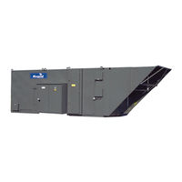
Rapid 4060 Installation, Operation & Service Manual (162 pages)
Rapid 4000 Series Direct-Fired Air Handler
Brand:
Rapid
| Category:
Air Handlers
| Size: 9.81 MB
Table of Contents
Table of Contents
3
Table of Contents
9
SECTION 1: Air Handler Safety
9
Description of Operation
9
Inspection and Setup
9
Temporary Storage
10
Safety Labels and Their Placement
10
California Proposition 65
10
Label Placement
11
Figure 1: 4024 - 4049
11
Figure 2: 4054 and 4089
12
Figure 3: 4000-Series Interior
13
SECTION 2: Installer Responsibility
14
Corrosive Chemicals
14
National Standards and Applicable Codes
14
Required Equipment
14
SECTION 3: Critical Considerations
16
Required Clearances to Combustibles
16
Hardware
16
Table 1: Recommended Torque Settings
16
SECTION 4: National Standards and Applicable Codes
17
Gas Codes
17
Installation Codes
17
Aircraft Hangars
17
Parking Structures and Repair Garages
17
Electrical
17
Venting
17
High Altitude
17
SECTION 5: Specifications
18
Table 2: 4000 am Dimensions
19
Figure 4: 4000 am Vertical Model Dimensions
19
Table 3: 4000 am Approximate Shipping Weights
20
Figure 5: 4000 am Horizontal Model Dimensions
20
Table 4: 4000 MUA Dimensions
21
Figure 6: 4000 MUA Vertical Model Dimensions
21
Table 5: 4000 MUA Approximate Shipping Weights
22
Figure 7: 4000 MUA Horizontal Model Dimensions
22
Table 6: 4000 FR Dimensions
23
Figure 8: 4000 FR Vertical Model Dimensions
23
Table 7: 4000 FR Approximate Shipping Weights
24
Figure 9: 4000 FR Horizontal Model Dimensions
24
Table 8: 4000 VAV Dimensions
25
Figure 10: 4000 VAV Vertical Model Dimensions
25
Table 9: 4000 VAV Approximate Shipping Weights
26
Figure 11: 4000 VAV Horizontal Model Dimensions
26
Table 10: Dimensions
27
Table 11: Leaving Dry Bulb Temperature Drop (Average)
27
Figure 12: Evaporative Cooling
27
Table 12: Air Density Ratio
28
Table 13: Dimensions
29
Table 14: Estimated Tons of Cooling
29
Figure 13: Mechanical Cooling
29
Table 15: Dimensions
30
Figure 14: Energy Recovery
30
Table 16: Energy Recovery
31
Table 17: Fan Selection Chart
32
Table 18: Fan Selection Chart (Continued)
33
Table 19: Static Pressure Drops for Options
34
SECTION 6: Lifting an Air Handler (Rigging)
35
Preparing to Lift the Air Handler
35
Lifting a Horizontal Air Handler
36
Figure 15: Lifting a Horizontal Air Handler Filter Section and Options (Model 4024 - 4049)
36
Figure 16: Lifting a Horizontal Air Handler with Options (Model 4054 - 4089)
36
Lifting an Vertical Air Handler
37
Figure 17: Lifting an Vertical Air Handler (All Models)
37
Figure 18: Lifting an Vertical Air Handler with Filter Section and Mixing Box
38
Upright Assembly Alignment
39
Figure 19: Inlet Alignment
39
SECTION 7: Air Handler Assembly
40
Caulking the Air Handler
41
Figure 20: Caulking Air Handler Joints
41
Caulking a Horizontal Air Handler
42
Figure 21: Caulking a Standard Horizontal Air Handler
42
Caulking an Vertical Air Handler
43
Figure 22: Caulking a Standard Vertical Air Handler
43
Figure 23: Assembling Optional Discharge / Supply and Return Sleeves
44
Accessory Connections
45
Figure 24: Electrically Connecting Joined Sections
45
Figure 25: Installing Cooling Coil Section
45
Figure 26: Installing Pressure Transmitter Tubing for am and VAV
46
Figure 27: Typical Freeze Protection (Evaporative Cooling Package #1)
46
Figure 28: Conductivity Control and Freeze Protection (Evaporative Cooling Package #2)
47
Figure 29: Protection and Auto-Flush (Evaporative Cooling Package #3)
47
Figure 30: Evaporative Cooling Trap Detail
48
SECTION 8: Roof Curb
49
Roof Curb Assembly and Installation
49
Table 20: Roof Curbs (Availability Based on Style)
49
Figure 31: Roof Curb
50
Figure 32: Roof Curb Installation
51
Figure 33: Roof Curb Assembly with Brackets
52
Figure 34: Duct Support Adapter
53
SECTION 9: Indoor Suspension Mounting - Horizontal Air Handler
54
Suspension Mounting Assembly and Instructions
54
Figure 35: Indoor Suspension
55
SECTION 10: Leg Mounting
56
Figure 36: Assembling Legs for Horizontal Air Handlers
57
Figure 37: Assembly Legs and Rainskirt for Upright Air Handlers
58
SECTION 11: Filter Section
59
Figure 38: Filter Section Support Assembly
59
SECTION 12: Inlet Hoods
60
Inlet Hood Assembly
60
Figure 39: Inlet Hood Without Filters (4024-4049)
60
Figure 40: Inlet Hood Without Filters (4054-4089)
61
Figure 41: Inlet Hood with Permanent Filters
61
Figure 42: Inlet Hood with Moisture Limiter
62
SECTION 13: Service Platform
63
Service Platform
63
Figure 43: Service Platform for an Vertical Air Handler
63
Figure 44: Service Platform for a Horizontal Air Handler
64
SECTION 14: Discharge Accessories
65
One-Way, Three-Way and Four-Way Discharge Head Installation
65
Figure 45: Vertical Air Handler with Duct Sleeves and Discharge Head
66
Figure 46: One-Way Discharge Head
67
Figure 47: Three-Way Discharge Head
68
Figure 48: Four-Way Discharge Head
69
Splash Plate Installation
71
Figure 50: Discharge Plate
71
SECTION 15: Vibration Isolation
72
Figure 51: Suspended
72
Figure 52: Curb Mounted
73
Figure 53: Platform Mounting on Vibration Isolators
74
Figure 54: Vibration Isolation Platform Locations
75
SECTION 16: Cooling Specifications
76
Evaporative Cooling
76
Table 21: Formulas
76
Table 22: Abbreviations
76
Table 23: Evaporation Rate
76
Table 24: Suggested Air Changes Per Hour (Air Change Method)
76
Table 25: Saturation Efficiency at Stated Media Depth
76
Table 26: Static Pressure Drop (in Wc) at Stated Media Depth
76
SECTION 17: Duct Considerations
77
Inlet Air Duct
77
Return Air Duct
77
Supply Air Duct Work
77
SECTION 18: Gas Piping
78
Gas Manifolds
78
Gas Piping and Pressures
78
Table 27: Manifold Component Identification
79
Figure 55: Standard Gas Manifold
79
Figure 56: FM Gas Manifold
80
Figure 57: XL Insurance Gas Manifold
81
Gas Piping
82
Pressure Test Ports
82
SECTION 19: Electrical
83
Disconnect Fuse Sizing
84
Wiring and Electrical Connections
84
Remote Panel
84
Motor Current Draw
84
Table 28: Minimum and Maximum Fuse Size by Motor Size and Supply Voltage
84
Table 29: Control Voltage Wiring for All Control Systems
84
Control Current Draw
85
Safety Systems
85
Table 30: Safety Systems
85
Interlocks
87
Control Options
87
Safety Systems
89
Table 31: Safety Systems
89
Remote Panels
90
Figure 58: Basic Remote
90
Figure 59: Basic Remote (Continued)
91
Figure 60: Standard Discharge Remote
92
Figure 61: Standard Discharge Remote (Continued)
93
Figure 62: Deluxe Room Control Remote
94
Figure 63: Deluxe Room Control Remote (Continued)
95
Figure 64: Standard Room Control Remote
96
Figure 65: Standard Room Control Remote (Continued)
97
DDC-Ready Controls
98
Figure 66: DDC-Ready Controls
98
Figure 67: DDC-Ready Controls (Continued)
99
Intelligent Control Systems
100
Figure 68: Air Handler Styles
101
HVAC Remote Panels and Panel Options
102
Basic Air Handler Sequence of Operation
104
Table 32: Factory Preset Schedule on TH8110 Thermostat
104
FIGURE 69: Fireye M4RT1
104
Table 33: Jumper Settings
106
Figure 70: Jumper Locations
106
Honeywell RM7890 Flame Safeguard
108
SECTION 20: Direct Fired Burner
120
Figure 71: Midco HMA-2A Burner
121
Direct Fired Burner Ignition
123
Figure 72: Spark Rod Dimensions
123
Direct Fired Burner Flame Proving (Flame Rod)
124
Figure 73: Maxon NPLE Burner
124
Honeywell UV Flame Detector
127
Honeywell UV Flame Detector (Continued)
128
SECTION 21: Start-Up Procedures
129
Installation of Recirculating Air Handler
130
Mechanical
130
Figure 74: Sheave Alignment
130
Electrical
131
Airflow
131
Table 34: Deflection Force B and BX Belts (in Lbs)
131
Figure 75: Belt Tension
131
Gas Piping and Initial Pressure Settings
132
Table 35: Motor Sheave Drive Torque Specifications
132
Table 36: Motor and Blower Bushing Torque Specifications
132
Figure 76: Fireye Flame Module
132
Table 37: Burner Mode by Amplifier Type
133
Safety Shut off Valve Check
134
Temperature Control System Calibration
134
Table 38: Maximum Temperature Rise
134
Figure 77: MR 212 Valve
135
Figure 78: M611 Valve
136
Figure 79: Regulator (2005)
136
SECTION 22: Maintenance
137
General
138
Unit Exterior
138
Blower Section
138
Manifold and Controls
140
Burner
140
Table 39: Motor Lubrication Intervals
141
Optional Equipment
142
SECTION 23: Replacement Parts
143
SECTION 24: Troubleshooting
144
Initial Checks
145
Motor and Blower
145
Burner
146
Temperature Controls
147
A1014 Amplifier - Field Checklist
148
Figure 80: RM7897C Flame Control
150
Section 25: Rapid
151
4000-Series Start-Up Procedures
151
Section 26: Rapid
156
4000-Series Start-Up Procedures Evaporative Cooler
156
Evaporative Cooler
159
SECTION 27: the RAPID
159
4000-Series Warranty
159
Advertisement
Advertisement
Related Products
Rapid 4066
Rapid 4044
Rapid 4036
Rapid 4049
Rapid 4054
Rapid 4024
Rapid 4073
Rapid 4080
Rapid 4040
Rapid 4089
Rapid Categories
Power Tool
Glue Gun
Nail Gun
Water Pump
Industrial Equipment
More Rapid Manuals
Login
Sign In
OR
Sign in with Facebook
Sign in with Google
Upload manual
Upload from disk
Upload from URL