Sign In
Upload
Manuals
Brands
PYE Manuals
Cordless Telephone
OLYMPIC M201
PYE OLYMPIC M201 Manuals
Manuals and User Guides for PYE OLYMPIC M201. We have
1
PYE OLYMPIC M201 manual available for free PDF download: Service Manual
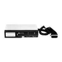
PYE OLYMPIC M201 Service Manual (101 pages)
Brand:
PYE
| Category:
Cordless Telephone
| Size: 9 MB
Table of Contents
Table of Contents
4
General Information
7
Summary of Data
7
Introduction
9
Equipment Variations
10
Module Identification
12
Installation and Operation
13
Pre-Installation Checks
13
Netting Procedures
13
Test Frequency Crystal Information
14
Contents List (Installation Items)
14
Equipment Required
14
Procedure
15
Fig. 2.1 Typical Installation
16
Fig. 2.2 Connection of 12V Supply
17
Fig. 2.3 Connection of 24V Supply
17
12V Supply
17
Fig. 2.4 Connection of Amplifier A200
18
Amplifier A200
18
Antenna Information
21
Fig. 2.6 Ancillary Items
23
Operation
25
Fig. 3.1 Receiver Block Diagram
27
Technical Description
27
Receiver Circuit Summary
27
Fig. 3.2 Transmitter Block Diagram
28
Transmitter Circuit Summary
28
Fig. 3.3 Power Supply Block Diagram
29
Power Supplies and Switching
29
Receiver RF Unit
30
Receiver Oscillator
32
Receiver Multiplier
32
10,7 Mhz Crystal Filter
33
IF Amplifier, Detector, and AGC Module
33
Noise Limiter, High and Low-Pass Filter
34
Squelch if and Delayed AGC Module
34
AF Amplifier Module
36
Noise Squelch Module
36
Low Power Transmitter Audio Module
37
High Power Transmitter Modulator Module
38
Transmitter Oscillator
38
PA Module
40
Antenna Filter Module
42
Switching Module
42
Regulator Module
43
Receiver and Transmitter Oscillator Module (8) - Single Channel
43
Receiver and Transmitter Oscillator Module (18) 12-Channel
44
Receiver and Transmitter Oscillator Module (18) 6-Channel
44
Precautionary Notes and General Information
46
Construction
47
Equipment Access
48
Fig. 4.1 Main Unit Interior View
48
Module Replacement
50
Crystal Information
50
Test Equipment
51
Alignment Procedures and Performance Checks
52
Fig. 4.2 Diode Probe Circuit Diagram
52
Receiver Alignment
54
Fig. 4.3 Test Extension Assemblies Kit
55
Receiver Performance Checks
57
Transmitter Alignment
58
Transmitter Performance Checks
60
Fault Location Checks - Transmitter
60
Fig. 4.4 Audio Test Lead
60
Detailed Signal Analysis of Receiver
62
Fault Location Checks - Receiver
64
Parts List
66
Notation
66
Ordering of Spare Parts
66
Abbreviations
66
Miscellaneous Items
67
Receiver Multiplier Module
68
Squelch if and Delayed AGC Module
68
Noise Squelch Module
76
Oscillator Module
77
Low Power Tx Audio Module
80
Tx Multiplier Module
81
Motherboard
86
High Power Tx Modulator Module
87
Optional Servicing Accessories
88
Fig. 6.1 Front and Rear Views of Equipment
93
Fig. 6.2 Control Module - Component Location Diagram
94
Fig. 6.4 Motherboard - Receiver Module Locations
96
Fig. 6.5 M201 Receiver Circuit
97
Fig. 6.6 Motherboard - Transmitter Module Locations
98
Fig. 6.7 M201 Transmitter Circuit
99
Fig. 6.8 Earlier Module Pwbs
100
Fig. 6.9 Circuit Variation Noise Squelch Module
100
Advertisement
Advertisement
Related Products
PYE Beaver M254
PYE Beaver M256
PYE PCT80
PYE Pocketphone PF1
PYE SBB130 F
PYE SBB130 M
PYE Categories
Cordless Telephone
Air Conditioner
Clock Radio
Transceiver
Amplifier
More PYE Manuals
Login
Sign In
OR
Sign in with Facebook
Sign in with Google
Upload manual
Upload from disk
Upload from URL