Sign In
Upload
Manuals
Brands
Pulnix Manuals
Security Camera
TM-4200CL
Pulnix TM-4200CL Manuals
Manuals and User Guides for Pulnix TM-4200CL. We have
1
Pulnix TM-4200CL manual available for free PDF download: Operation Manual
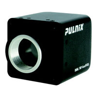
Pulnix TM-4200CL Operation Manual (70 pages)
Progressive scan camera
Brand:
Pulnix
| Category:
Security Camera
| Size: 2 MB
Table of Contents
Table of Contents
5
1 Software Use and Installation Introduction
11
Software Installation
11
Before Installing Dual-Tap Accupixel Series Camera-Control Software
11
Installing the Software
12
FIGURE 1. Setup Installs Dual Tap Accupixel
12
Installing the Camera Link API DLL (Clserxxx.dll)
13
Running Dual Tap Accupixel
13
FIGURE 2. Accupixel Setup Screen
13
FIGURE 3. Follow the Installation Directions
13
Uninstalling the Software
14
FIGURE 4. the Screen Grabber Has an Essential .Dll File
14
FIGURE 5. "Add or Remove Programs" Utility Uninstalls Older Software
15
2 TM/TMC-4200CL Camera
16
FIGURE 6. Back of the TM/TMC 4200CL
16
3 Graphical User Interface
17
GUI Features
17
FIGURE 7. Main Dualtap Accupixel Window
17
Using the Camlink Mode
18
Gige Mode
18
FIGURE 8. Setting up Camlink
18
FIGURE 9. Choose the Desired Frame Driver .Dll
18
FIGURE 10. an Error Message Appears if the .Dll Application Is Missing
18
Operating the Control Software
19
Check Current Camera Setting
19
Exposure Control
19
FIGURE 11. the Report Frame Is Near the Bottom of the Window
19
FIGURE 12. Continuous Mode Operates the Shutter from the Camera Settings
19
FIGURE 13. Trigger Mode Uses a Manual or Sensor Command to Operate the Shutter
20
FIGURE 14. to Use Programmable Shutter Speed, Select Programmable
20
FIGURE 15. the Scan Area Drop down Box
21
FIGURE 16. Enter the Starting Line Number for a Programmable Scan
21
FIGURE 17. Click the Apply Button after Programming the Scan
21
Gain Control
22
Offset Voltage
22
FIGURE 18. Gain Is Being Set if the R Auto Gain Box Appears Checked
22
FIGURE 19. R Auto Offset Box Is Checked Only While the Camera Sets the Command
22
Video Depth
23
Image Pre-Processing
23
Ctrl Signals
23
FIGURE 20. Click the Corresponding Option Button to Set the Tap
23
FIGURE 21. Click the Option Button to Select Video Depth
23
FIGURE 22. Checking "Enable Blemish Compensation" Activates Image Pre-Processing
23
FIGURE 23. Set "Ctrl Signal" by Clicking the Option Button Matching Your Cabling
23
Trigger
24
LUT (Look-Up Table)
24
FIGURE 24. Set "Trigger" by Clicking the Desired Option Button
24
FIGURE 25. Set "Positive" or "Negative" LUT
24
FIGURE 26. Table Drop down Menu
24
FIGURE 27. Gamma.45 Imitates Human Eye Sensitivity When Creating an Image
25
FIGURE 28. the Knee Setting Activates When "Send Knees" Is Clicked
25
Report Section
26
Main Menu: "Option
26
FIGURE 29. the Report Frame Shows the Recent Camera Actions
26
FIGURE 30. a Table Helps Users Understand the Report Screen
26
Eeprom
27
FIGURE 31. Use the "Option" Menu to Access the Test Pattern
27
FIGURE 32. Use the "Option" Menu to Access the Test Pattern
27
Main Menu "Connectivity
28
Main Menu "About
28
Exit
28
FIGURE 33. Use the "Connectivity" Menu to Set Buffer Size
28
FIGURE 34. the "About" Menu Provides Hardware and Software Information
28
4 Hardware Introduction
29
Product Description
29
Features
30
System Configuration
31
FIGURE 35. CL (Camera Link) System Configuration
31
5 Installation
32
Getting Started
32
Unpacking Instructions
32
Components List
32
Accessories and Options
32
Camera Setup
32
Heat Dissipation
32
Connector Pin Configurations
33
FIGURE 36. Hirose Connector
33
TABLE 1. 12-Pin Connector
33
FIGURE 37. 26-Pin Camera Link Connector
34
FIGURE 38. BNC Connector
34
TABLE 2. Connector and Pin-Out Configurations
34
Camera Link Cable
35
Power Supplies and Power Cable Setup
35
FIGURE 39. 3M Camera Link Cable
35
FIGURE 40. 12P-02S Interface Cable (Optional)
36
FIGURE 41. 12P-02S Interface Cable Pin out
36
Attaching the Analog Video Output
37
Attaching the Camera Lens
37
6 Functions and Operations
38
Camera Rear Pane
38
Digital I/O Connector (Camera Link)
38
Analog Output Connector
38
Power and External Sync Connector
38
FIGURE 42. Camera Connectors
38
Sensor Layer and Timing
39
FIGURE 43. Digital Video Output
39
FIGURE 44. Camera Timing Chart
40
FIGURE 45. Digital Data Output Order for Configuration
40
Scan Area
41
Preset Scan Area
41
FIGURE 46. Field Video Timing--Continuous Mode
41
Programmable Scan Area
42
Full Scan Area 2X2 Binning
43
FIGURE 47. Bayer
43
FIGURE 48. Bayer
43
Sub-Sampling Digital Zoom
44
FIGURE 49. 2X2 Binning
44
FIGURE 50. Sub-Sampling Digital Zoom
45
FIGURE 51. Sub-Sampling Digital Zoom 2X
45
FIGURE 52. Sub-Sampling Digital Zoom 3X
46
FIGURE 53. Sub-Sampling Digital Zoom 4X
47
TABLE 3. Scan Area Start Points
47
Electronic Shutter
48
Preset Shutter
48
Programmable Exposure-Continuous Mode
48
Asynchronous no Shutter Mode
48
TABLE 4. Electronic Preset Shutter
48
Asynchronous Programmable Exposure Mode
49
FIGURE 54. External Trigger Timing
49
Pulse Width Control Mode
50
FIGURE 55. Asynchronous Programmable External Trigger
50
Particle Imaging Velocimetry Fixed Exposure Mode
51
FIGURE 56. Pulse Width Control Trigger
51
FIGURE 57. PIV Exposure Timing Table
51
PWC PIV Mode
52
FIGURE 58. PWC PIV Timing Table
52
TABLE 5. Timing Chart
52
Dynamic Range Control
54
FIGURE 59. Output and Blooming
54
TABLE 6. Asynchronous Mode Chart
54
Programmable Look-Up Table (LUT) and Knee Control
55
External Sync and Pixel Locking
56
7 Serial Communication Kit
57
TM-4200CL Command List
58
TABLE 7. TM-4200CL Command List
58
TABLE 8. TM-4200CL Command Response Table
61
8 Problems and Solutions
64
Symptom: no Video
64
Symptom: Dark Video
64
Symptom: Non-Synchronized Video
64
Information and Support Resources
65
9 Appendix
66
Specifications
66
TABLE 9. TM-4200CL Camera Specifications Table
66
FIGURE 60. Physical Dimensions
67
FIGURE 61. Spectral Response
67
Spectral Response
67
TM-4200CL Physical Dimensions
67
Advertisement
Advertisement
Related Products
Pulnix TM-5LC
Pulnix TMC-6700 Series
PULNiX TM-6CN
PULNiX TM-72EX
Pulnix TM-75
Pulnix TM-76
Pulnix TMC-7
Pulnix TMC-6
PULNiX TMC-7DSP
Pulnix TM-1402 series
Pulnix Categories
Security Camera
Digital Camera
IP Camera
Color Camera
Network camera
More Pulnix Manuals
Login
Sign In
OR
Sign in with Facebook
Sign in with Google
Upload manual
Upload from disk
Upload from URL