Sign In
Upload
Manuals
Brands
Protherm Manuals
Controller
E8.4401
User Manuals: Protherm E8.4401 Cascade Controller
Manuals and User Guides for Protherm E8.4401 Cascade Controller. We have
1
Protherm E8.4401 Cascade Controller manual available for free PDF download: Operating Instructions Manual
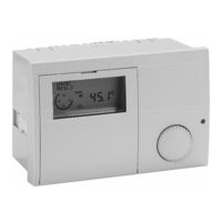
Protherm E8.4401 Operating Instructions Manual (60 pages)
System Manager
Brand:
Protherm
| Category:
Controller
| Size: 1 MB
Table of Contents
T-Room des
1
General Information
2
Safety Information
2
Power Connection Regulations
2
Warranty Conditions
2
Important Text Passages
2
Description
2
Declaration of Conformity
2
Function
2
Table of Contents
3
Contents
3
Part 1: Operation
6
Operation in Normal Mode
6
Operating Elements
6
Ç Operating Mode Selection
6
Effect of the Operating Mode
7
Display in Normal Operation
8
Changing the Settings
9
Operating Elements
9
Operating Level
10
Areas
11
General
11
Display
11
Users
11
Time Programs
11
Expert
11
Levels
11
Installation
11
Hot Water
11
Heating Circuit I
11
Part 2: Overview of Display Values and Settings
12
General Area
12
Date/Time/Holiday
12
Service
14
Code Number Entry
14
Relay Test
14
Sensor Test
15
Sw no XXX-XX
16
CASCADE MANU (Only with Code No.)
16
BURNER TIME and BURNER START
16
Limiter Test
16
Service
17
Reset
17
Display Range
18
Installation
18
T-Outside
18
T-COLL des ((Heat Request)
18
Hot Water
19
T-DHW RATED (Hot Water Set Temperature)
19
T-ROOM des a (Current Value for Set Room Temperature)
19
T-ROOM (Room Temperature)
19
User Area
20
Installation
20
GERMAN => Language
20
Contrast
20
Display Sel
20
Selec-Prog
20
Hot Water
21
DHW (1X Hot Water)
21
T-DHW 1-3 (Hot Water Temperature Setting)
21
Hot Water Short Time Heating Function
21
Heating Circuit I / II
22
Mode
22
T-Reduced
22
T-Absence
22
T-LIMIT DAY/T-LIMIT N (Day/Night)
23
Heatslope
23
ADAPTION (Heat Slope Adaptation)
24
ROOMS-INFL (Room Sensor Influence)
24
ADAP ROOM-T (Room Sensor Adaptation)
24
OPTIM HEAT (Heating Optimisation)
25
MAX OPT-TIME (Maximum Bringing Forward)
25
ECONO OPTI (Reduction Optimisation)
25
Pc-Enable
25
Return
25
Timer Program Area
26
List of Available Time Programs
26
Selecting a Timer Program
26
Timer/Heating Program Adjustment
27
Expert Area
30
Installation
30
Code-No
30
BUS ID 1 / 2 (Heating Circuit Number)
30
Time Master
30
MAX T-COLL (Max. Header Temperature)
30
MIN T-COLL (Min. Header Temperature)
30
Hyst Boiler
31
(Dyn. Switching Hysteresis Stage 1)
31
With HYST TIME (Hysteresis Time)
31
CAP/MODULE (Boiler Output for each Stage)
32
MIN MOD CASC (Min. Modulation Cascade)
32
Hw-Boiler
32
(Number of Stages for HW Operation)
32
CONTROL DEVIAT (Header Control Variance)
33
DES OUTPUT (Required System Output [In %])
33
Switch Val (-99 - +99)
33
BLOCK TIME (Currently Remaining Value)
33
RESET TIME (Resetting Time for I-Controller)
34
Sequence 1)
34
SEQUENCE 2 (Heat Generator Sequence 2)
34
BOILER SEQ (Time to Sequence Change)
34
LOCK TIME (Delay Time for Next Stage)
34
Screed Program
35
SCREED (Activation of Screed Drying Process)
35
Hot Water
36
DHW RELIEF(Charging Pump Lock)
36
PARALLEL (Pump Parallel Running)
36
T-Boiler Dhw
37
(Increase During HW Operation)
37
HYST DHW (Hot Water Hysteresis)
37
DHW FOLLOWUP (Pump Run-Down Time)
37
THERM INPUT (Storage Tank with Thermostat)
37
WALL HUNG (for Modulating HS)
37
Heating Circuit I / II
38
Hc Function
38
(Heating Circuit Function Selection)
38
PUMP MODE (Pump Operating Mode)
39
MIXER OPEN (Open Mixer Dynamic)
39
MIXER CLOSE (Close Mixer Dynamic)
40
MAX T-FLOW (Max. Flow Temperature)
40
MIN T-FLOW (Min. Flow Temperature)
40
T-FROST PROT (Frost Protection Temperature)
40
OUT-TEMP-DEL (Outside Temperature Delay)
40
SLOPE OFFSET (Heating Slope Distance)
41
B-HEAT SINK (Circuit Enable)
41
Part 3: General Function Description
41
Heat Circuit Control
41
Weather-Dependent Control
41
Room Sensor Influence
41
Hot Water Generation
42
Frost Protection Function
42
EEPROM Check
42
Circulation Pump Control
43
Switched According to Heating Requirement
43
Switched According to Heating Limits
43
Delayed Pump Switch-Off
43
Pump Blocking Protection
43
Mixer Motor Blocking Protection
43
Part 4: Installation and Start-Up
44
Installation
44
Assembly / Dismantling
44
Connecting Instructions
45
System Diagram with Direct Heating Circuit
46
System Diagram with Header Pump
47
Connection Diagram
48
Terminal Assignment
48
Remote Controls
49
Operation-Control Module BM 8
49
Remote Control FBR2
49
Sensor Resistances FBR
50
DCF Receiver
50
Maximum Delimiter
51
Telephone Switch
51
Sensor Values / Characteristic Curve
52
Outdoor Sensor AF (AFS) S
53
Boiler Sensor KF (KFS) H
53
Flow Sensor VF (VFAS) V
54
Storage Tank Sensor SPF (SPFS) F
54
Commissioning
55
Commissioning Procedure
55
System Bus
56
The Heating System
56
Bus ID
56
Error Messages
57
Troubleshooting
58
Technical Data
59
Advertisement
Advertisement
Related Products
Protherm Categories
Boiler
Thermostat
Heater
Measuring Instruments
Controller
More Protherm Manuals
Login
Sign In
OR
Sign in with Facebook
Sign in with Google
Upload manual
Upload from disk
Upload from URL