Sign In
Upload
Manuals
Brands
ProMATIC Manuals
Controller
CMP25-2
ProMATIC CMP25-2 Controller Manuals
Manuals and User Guides for ProMATIC CMP25-2 Controller. We have
1
ProMATIC CMP25-2 Controller manual available for free PDF download: Manual
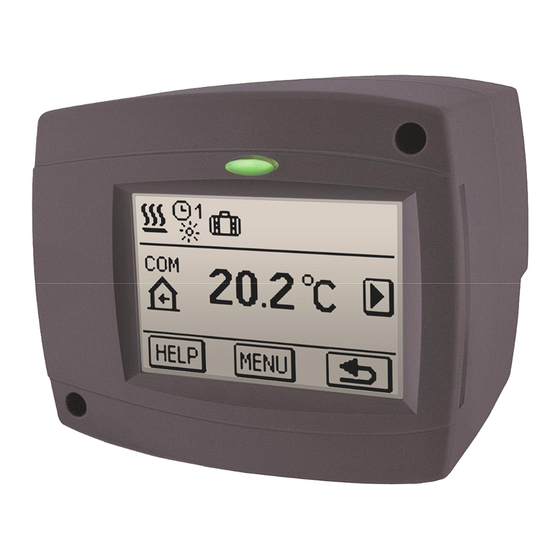
ProMATIC CMP25-2 Manual (184 pages)
Weather compensated controller for mixing heating circuits
Brand:
ProMATIC
| Category:
Controller
| Size: 5 MB
Table of Contents
English
6
Table of Contents
6
User Manual
8
Controller Description
8
Controller Appearance
8
Operation Mode Indication
8
Initial Setup of Controller
9
Procedure of Initial Setup
9
Main Display and Navigation
11
Main Display Description and Design
11
Description of Symbols Shown on Display
11
Symbols for Operation Mode
11
Symbols for User Functions
12
Symbols for Temperature Ans Data Overview
12
Symbols for Protection Functions
13
Symbols for Communication of Controllers in Network
13
Symbols for Notice and Warnings
13
Basic Screen Navigation
14
Locking / Unlocking the Screen
14
Display for Help, Notices and Warnings
15
Entry and Navigation through the Menu
16
Menu Structure and Description
17
Temperture Settings
20
User Functions
21
Operation Mode
22
Time Programs
23
Basic Settings
26
Data Overview
27
Service Settings Manual
28
Service Settings
28
Basic Parameters
28
Heat Curve
30
Service Parameters
32
Floor Drying Parameters
35
Factory Settings
36
Controller Installation
37
Installation Onto Mixing Valve
37
Controller's Electric Connection
39
Connection of Mains
39
Connection of Sensors, Room Units and BUS
39
Connection of Digital Room Unit DD2
40
Connection of Room Sensor
40
Marking and Installation of Temperature Sensors
41
Operation Mode by Sensor Failure
42
Expanding the System on Multiple Heating Circuits
42
Installation Manual
37
Hydraulic and Electric Schemes
44
Technical Data
47
Conformity with Standards and Directives
48
Declarations and Statements
48
Disposal of Old Electrical & Electric Equipment
48
Deutsch
50
Beschreibung des Reglers
52
Aussehen des Reglers CMP25-2
52
Bedienungs- und Einstellungsanleitungen
52
Betriebsartsignalisierung
52
Reglereinstellung bei der Ersten Inbetriebnahme
53
Verlauf der Einstellung
53
Aussehen des Displays
55
Beschreibung der Symbole am Display
55
Symbole zur Darstellung der Betriebsart des Reglers
55
Symbole zur Darstellung der Benutzerfunktionen
56
Symbole zur Darstellung der Temperatur und anderen Daten
56
Symbole zur Darstellung der Schutzfunktionen
57
Symbole zur Darstellung der Kommunikation der Angeschlossene Geräte
57
Warnsymbole
57
Grundnavigation IM Display
58
Display Ent- und Zusperren
58
Graphischer Lcd Display
55
Hilfebildschirm, Meldungen und Warnungen
59
Offnen des Menüs und der Navigation
60
Menüstruktur und Menübeschreibung
61
Temperatureinstellung
64
Benutzerfunktionen
65
Betriebsartenwahl
66
Zeitprogramme
67
Grundeinstellungen
70
Daten Kontrolle
71
Wartungsanleitungen
72
Reglerparameter
72
Grundparameter
72
Heizkurve
74
Wartungsparameter
76
Die Parameter der Estrichtrocknung
79
Werkseinstellungen
80
Montage auf das Mischventil
81
Montage des Reglers
81
Elektrisches Anschluss des Reglers
83
Anschlusse für die Stromversorgung
83
Anschlusse für Fühler und BUS Verbindungen
83
Anschluss der Raumeinheit DD2
84
Anschluss des Raumfühlers
84
Montagebeschreibung und Temperaturfühlerbezeichnung
85
Betriebsbeschreibung bei Fühlerstörung
86
Systemerweiterung auf Mehrere Heizkreise
86
Hydraulikschemen
88
Technische Daten
91
CE-Konformitätserklärung
92
Entsorgung von Gebrauchten Elektrischen und Elektronischen Geräten
92
Erklärungen und Garantie
92
Italiano
94
Descrizione del Regolatore
96
Aspetto del Regolatore PROMATIC CMP25-2
96
Indicazione DI Funzionamento
96
Istruzioni Per L'uso
96
Configurazione del Regolatore al Primo Avvio
97
Configurazione Delle Impostazioni
97
Descrizione Dei Simboli Visualizzati Sul Display
99
Simboli Per la Visualizzazione del Funzionamento
99
Simboli Per la Visualizzazione Delle Funzioni Impostate Dall'utente
100
Simboli Per la Visualizzazione Delle Temperature E Degli Altri Dati
100
Simboli Per Le Funzioni Impostate Dall'utente
101
Simboli Per la Visualizzazione Della Comunicazione Tra Le Apparecchiature Collegate
101
Simboli Per Le Comunicazioni E Le Avvertenze
101
Descrizione E Aspetto Dello Schermo
99
Display Lcd Grafico
99
Blocco E Sblocco del Display
102
Navigazione DI Base Sul Display
102
Schermo Per L'aiuto, Le Comunicazioni E Le Avvertenze
103
Accesso E Navigazione Nel Menù
104
Struttura E Descrizione del Menù
105
Impostazione Delle Temperature
108
Funzioni Dell'utente
109
Modalità DI Funzionamento
110
Programmi Orari
111
Impostazioni DI Base
114
Controllo Dei Dati
115
Istruzioni Per Le Impostazioni DI Servizio
116
Parametri del Regolatore
116
Parametri Generali
116
Curva Climatica
118
Parametri DI Servizio
120
Parametri Per L'asciugatura del Massetto
123
Impostazioni DI Fabbrica
124
Installazione del Regolatore
125
Installazione Sulla Valvola DI Miscelazione
125
Dichiarazione del Produttore DI Conformità del Prodotto
126
Allacciamento Elettrico del Regolatore
127
Adattatori Per Tensioni DI Rete
127
Adattatori Per Sensori E Connessione BUS
127
Allacciamento del Sensore da Interno
128
Allacciamento Dell'unità Digitale Interna DD2
128
Modalità DI Installazione E Indicazione Dei Sensori DI Temperatura
129
Ampliamento del Sistema a Più Circuiti DI Riscaldamento
130
Modalità DI Funzionamento in Caso DI Guasto Dei Sensori
130
Istruzioni Per L'installazione
125
Schemi Idraulici Ed Elettrici
132
Dati Tecnici
135
Annotazioni
136
Dichiarazioni E Garanzia
136
Smaltimento Apparecchiature Elettriche Ed Elettroniche in Disuso
136
Advertisement
Advertisement
Related Products
PROMATIC WDC Series
PROMATIC WDC10
PROMATIC WDC10B
PROMATIC WDC20
ProMATIC Categories
Accessories
Controller
Sports & Outdoors
Utility Vehicle
Receiver
More ProMATIC Manuals
Login
Sign In
OR
Sign in with Facebook
Sign in with Google
Upload manual
Upload from disk
Upload from URL