Sign In
Upload
Manuals
Brands
PRO AIR Manuals
Measuring Instruments
TPK 21
PRO AIR TPK 21 Manuals
Manuals and User Guides for PRO AIR TPK 21. We have
2
PRO AIR TPK 21 manuals available for free PDF download: Functional Description And Operating Instructions
PRO AIR TPK 21 Functional Description And Operating Instructions (132 pages)
Pressure Dew Point Monitoring Devices
Brand:
PRO AIR
| Category:
Measuring Instruments
| Size: 41 MB
Table of Contents
Table of Contents
2
Scope of Delivery
6
General Dangers and Precautions
7
Safety Instructions for Electrical Connection
7
Safety Instructions for Compressed Air Systems
8
Avoiding Damage to the Measuring Probe
9
Calibration and Measuring Accuracy
9
Important Application Notes
9
Function
10
Humidity Measurement in Compressed Air Systems
10
Intended Application
10
Application Notes
11
Mounting of the Device
11
Safety Instructions
11
Mounting
12
Procedure for Installation
12
Connection at the Compressed Air Network
13
Direct Stationary Assembly at the Compressed Air Line
13
Stationary Assembly Via Hose
13
Application of a Pre-Filter / Water Separator
14
Mounting Examples
14
Adjustment of Measurement Chamber Choke
15
Connection of Power Supply
16
For the Rarest of the Cases
17
TPK Start-Up
17
Operation
18
Views of Unit
18
Front View
19
Connection to Power Supply
20
View (from Below)
21
Display
21
Description of Display
22
Side View (from the Right)
20
Description of Main Screen
22
Description Info Screen
23
Adjustment of Display Fields
24
Possible Display Variation Concerning the Different Fields
25
Personalising Password
27
Adjustment of National Languages
32
Information
35
Switching the Heating(Heater) System on and off
38
Factory Settings
41
Outputs
44
Touchscreen Calibration
49
Measurement Value Simulation
52
Statistics Reset
57
Reset Fault Memory
60
Filter
63
Units Setting
66
Setting the Date / Time
69
Setting the Date
69
Setting the Time
73
Configuration of Relay Adjustments
77
Setting Source (Output Parameters)
79
Setting the Relay Switching Characteristics
80
Setting the Limit Values
81
Configuration of Analog Output
83
Selection of Desired Source (Output Parameter)
85
Selection of the Desired Analog Output Value
86
Configuration of Lower Analog Output Value
87
Configuration of Upper Analog Output Value
88
Configuration of Alarm Output
89
Setting of Desired Alarm Value
90
Setting of Desired Measurement - Channel (Source)
90
Setting Pre-Alarm
92
Setting Main-Alarm
97
Setting Delay
102
Setting of Desired Alarm Value
104
Technical Datas
105
Dimensions
107
Modbus
108
Supported MODBUS Features
108
Supported MODBUS Commands
108
Function Code 1 - Read Coils
109
Function Code 17 - Report Slave ID
109
Function Code 3 - Read Holding Registers
109
Function Code 5 - Write Single Coil
109
Exceptions Returned
110
Holding Registers Memory Mapping
110
Function Code 16 - Write Multiple Register
110
Function Code 6 - Write Single Register
110
General Holding Registers Mapping
111
General Coils Mapping
114
Project Specific Coils Mapping
114
Data Logging
115
Appendix
118
Menu Structure
119
Project Specific Holding Registers Mapping
114
Coil Address Memory Mapping
114
Menu Item: Main
119
Menu Item: out
120
Menu Item: Alarm
121
System References and Messages
122
EG-Conformance Details
123
Guarantee
123
Accessories
124
Connecting Optional Accessories
125
PIN - Assignment for Conctor
126
Voltage Supply from an External Source of Supply
129
Trouble Shooting Guide
130
The Measured Value Is Flow Dependent and too High (I.e. too Humid)
130
The Measured Value Is too High (I.e. too Humid)
130
The Measured Value Is too Low (I.e. too Dry)
131
The Measured Value Varies Significantly
131
Service and Calibration
132
Advertisement
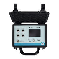
PRO AIR TPK 21 Functional Description And Operating Instructions (127 pages)
Portable Pressure- and Dew-Point Monitoring Device
Brand:
PRO AIR
| Category:
Measuring Instruments
| Size: 3 MB
Table of Contents
Table of Contents
2
Scope of Delivery
5
General Dangers and Precautions
6
Safety Instructions for Electrical Connection
6
Safety Instructions for Compressed Air Systems
7
Important Application Notes
8
Avoiding Damage to the Measuring Probe
8
Calibration and Measuring Accuracy
8
Intended Application
9
Humidity Measurement in Compressed Air Systems
9
Function
9
Mounting of the Device
10
Safety Instructions
10
Application Notes
10
Procedure for Installation
11
Mounting
11
Connection at the Compressed Air Network
12
Direct Stationary Assembly at the Compressed Air Line
12
Application of a Pre-Filter / Water Separator
13
Mounting Examples
13
For the Rarest of the Cases
15
Operation
16
Views of Unit
16
Top View (Open Box)
16
Display
18
Description Info Screen
21
Adjustment of Display Fields
22
Possible Display Variation Concerning the Different Fields
23
Personalising Password
25
Adjustment of National Languages
30
Information
35
Switching the Heating(Heater) System on and off
36
Factory Settings
39
Outputs
42
Touchscreen Calibration
47
Measurement Value Simulation
50
Statistics Reset
55
Reset Fault Memory
58
Quit Alarm
61
Quit Service Request
64
Filter
67
Units Setting
70
Setting the Date / Time
73
Setting the Date
73
Setting the Time
77
Configuration of Relay Adjustments
81
Setting Source (Output Parameters)
83
Setting the Relay Switching Characteristics
84
Setting the Limit Values
85
Configuration of Analog Output
87
Selection of Desired Source (Output Parameter)
89
Selection of the Desired Analog Output Value
90
Configuration of Lower Analog Output Value
91
Configuration of Upper Analog Output Value
92
Configuration of Alarm Output
93
Setting of Desired Alarm Value
94
Setting of Desired Measurement - Channel (Source)
94
Setting Pre-Alarm
96
Setting Main-Alarm
101
Setting Delay
106
Setting of Desired Alarm Value
108
Technical Datas
109
Modbus
111
Supported MODBUS Features
111
Data Logging
112
Appendix
115
Menu Structure
116
Menu Item: Main
116
Menu Item: out
117
Menu Item: Alarm
118
System References and Messages
119
EG-Conformance Details
120
Guarantee
120
Accessories
121
Connecting Optional Accessories
122
PIN - Assignment for Conctor
123
Voltage Supply from an External Source of Supply
125
Setting Examples
126
Setting Example: Dew Point Control
126
Setting Example: Minimum Pressure Control
127
Advertisement
Related Products
PRO AIR TPK 21 LT
PRO AIR TPK 41
PRO AIR TPK 61
PRO AIR FGP Series
PRO AIR FGP-1
PRO AIR FGP-2
PRO AIR FGP-3
PRO AIR FGP-4
PRO AIR Categories
Measuring Instruments
More PRO AIR Manuals
Login
Sign In
OR
Sign in with Facebook
Sign in with Google
Upload manual
Upload from disk
Upload from URL