Sign In
Upload
Manuals
Brands
Preferred Instruments Manuals
Controller
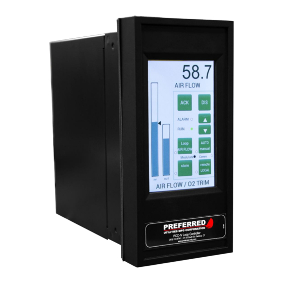
PCC-IV
Preferred Instruments PCC-IV Manuals
Manuals and User Guides for Preferred Instruments PCC-IV. We have
1
Preferred Instruments PCC-IV manual available for free PDF download: Instruction Manual
Preferred Instruments PCC-IV Instruction Manual (135 pages)
Brand:
Preferred Instruments
| Category:
Controller
| Size: 7 MB
Table of Contents
Section 1 - Product Overview
9
Table of Contents
9
Benefits
10
Product Description
10
Features
10
Com-Link Data Highway Concepts
11
Distributed Control System Concepts
11
Configuration Concepts
11
Analog and Discrete Control Functions
11
Blockware Concepts
12
Library of Functions
12
Any-Function-Any-Block
12
Reusable Functions
12
Softwiring
12
Blocks
12
Triac Output for Electric Actuators (Option Cards)
13
High-Temperature Hot-Water (HTHW) Btu/Hr Computation
13
Gas Flow Pressure/Temperature Compensation
13
Steam Flow Pressure Compensation
13
Boiler Efficiency
13
Learn Mode
13
Multiple F(X)
13
Special Option Card and Special Function Block Capabilities
13
Service Manual and Block Forcing
13
Drum Level Pressure Vs. Density Compensation
14
Oxygen Sensor Control/Signal Conversion (Option Card)
14
Relay Output Channels
14
Flow Totalization
14
PCC IV Loop Controller Model Number
15
Option Board Input / Output Expansion Examples
15
Spare Parts List
16
Operator Control Panel
17
Communications
17
Input/Output (Standard - no Option Cards)
17
Performance
17
PCC-IV Specifications
17
Environmental
17
Electrical
17
Mechanical
17
Section 2: Installation
18
Ambient Temperature
19
Mounting Overview
19
NEMA 13 / IP65 Environment
19
Option Board Descriptions
19
Rear Access
19
Mounting
20
Panel Cutout Dimensions
20
PCC-IV Dimensions
20
120 Vac Ground
21
24 VDC Redundant Power Input Terminals
21
Shielded Cable
21
Terminal Blocks
21
Wire Type
21
Wiring Overview
21
Connecting and Powering the Front Panel
22
24 VDC & 5 VDC Power Supply Load Calculations
23
Fuses
23
250-Ohm Resistors for 4-20 Ma Inputs
24
A" Option Board 250-Ohm Switches
25
Rev. 0: "B" Option Board, 250-Ohm Switches
25
Rev. A: "B" Option Board, 250-Ohm Switches
25
F" Option Board 250-Ohm Switches
26
G" Option Board Fuses and Pull-Ups
26
J" Option Board Isolated Neutral Jumpers
27
S" Option Board 120 Vac Fuse
27
CPU Board Layout
28
CPU Board Field Wiring Terminals
29
Option Board Field Wiring Terminals
30
Four Wire 4-20 Ma Input
31
Two Wire 4-20 Ma Input, External 24 VDC
31
Two Wire 4-20 Ma Input, Internal 24 VDC
31
Wiring Examples
31
1-5 VDC Input
32
Isolated 4-20 Ma Input
32
4-20 Ma Output
33
Potentiometer Input
33
Potentiometer Input, "G" Board
33
120 Vac Discrete Inputs, "J" Board
34
120 Vac Discrete Inputs, CPU Board
34
Discrete Output, Sinking, External 24 VDC
35
Discrete Output, Sinking, Internal 24 VDC
35
Relay Output
35
Triac Output, Other AC Loads
36
Triac Output, Reversible Actuator
36
DC Commons and AC Neutrals Isolation
37
Pull-Up/Down Resistor for Voltage Inputs
39
RS485 Communications Wiring
40
Ethernet Cables
42
Micro-USB Download Cable
42
Field Installation of Option Boards
43
Section 3 Operation
44
General
45
Operator Controls and Front Panel Usage
45
Front Panel Displays and Soft-Buttons
46
OUT Bargraph
46
RUN Light
46
SP Arrow
46
And ▼ Rate of Change
47
And ▼ Soft-Buttons
47
DIS Soft-Button
47
Message Display
47
Numeric Display
47
Auto/Manual Example
48
Auto/Manual Soft-Button and Light
48
ACK Soft-Button and the Alarm Annunciator
49
ALARM Light
49
Multiple Loops
49
User Defined Lights
49
User Defined Soft-Buttons
49
Section 4: Menu Operations
51
Introduction
52
Entering the Main Menu
53
Menu Tree
53
Last Parameter
54
Main Menu
54
Quick Parameters Menu
54
Service Manual Menu
55
What Is "Service Manual" (S/M) Mode
55
Change One Output to S/M or Auto
56
Changing an Output Value in S/M Mode
56
Entering Service Manual (S/M)
56
Set All Outputs to Auto
56
Set All Outputs to S/M
56
Enabling the Password System
57
Password Levels
57
Password Menu
57
The Change Password Soft-Button
57
Browse Blocks Menu
58
Disabling the Password System
58
General
58
Change a Parameter
59
Forcing Block Outputs
59
How to Use Browse Blocks
59
Navigation
59
Set Clock Time/Date Menu
60
Utilities Menu
60
Calibrate I/O Menu
61
Memory Menu
61
Save Config Changes
61
When Is Calibration Required
61
Analog Input Calibration Procedure
62
Analog Output Calibration Procedure
63
Calibrate Touch
64
Clean Screen
64
Enable Buzzer
64
Screen Utilities Menu
64
Choose Theme
65
M4 Messages Menu
65
Modbus Ports
65
Set Touch Sensitivity
65
Baud Rate
66
Data
66
Device Address
66
Ethernet Port 0 (or 1)
66
Ipv4 Address
66
Ipv4 Mask
66
Parity
66
RS485 Port
66
Rtu/Ascii
66
Ipv4 Gateway
67
Supported Modbus Functions
67
Table of Contents
68
Any-Function-Any-Block
69
Blocks
69
Blockware Basics
69
Library of Functions
69
Reusable Functions
69
Softwiring
69
PCC-IV Blocks
70
Block
71
Blockware Configuration
71
Function Type or Function Code Number
71
Input
71
Parameter
71
PCC-IV Terminology / Glossary
71
A5 Core
72
Analog
72
Discrete
72
Eeprom
72
M4 Core
72
Nand
72
NVRAM Retentive Memory
72
Ram
72
Configuring Blockware Control Logic
73
Using Pc4_Draw
73
Anatomy of a Block
74
Connection Points and Softwiring
74
Connectors
75
Search and Replace
75
Modifying the Front Panel Settings
76
Writing a Configuration to the PCC-IV
77
Exporting OIT Tags
78
Good Control Strategy
78
Reading a Configuration from the PCC-IV
78
Viewing Live Values
78
Flashing/Updating Firmware
79
Break the Configuration down into Manageable Sections
81
Check the I/O Count
81
Define the Requirements
81
Modifying a Blockware Configuration
81
Drag the Blocks Needed for each Section to the Canvas, Assign Block Numbers, and "Softwire" the Block Inputs
82
Modify Parameters as Required
83
Add Tags Necessary for Setting up the Panel Data Screen And/Or OIT & SCADA Communication
84
Configure the Front Panel Displays and Alarms
84
Place the Controller into Operation
85
Test the Configuration
85
Section 6: Blockware Functions - Technical Reference
86
F0 [A0] Analog Constant, 0.00
89
F2 [AIN] Analog Input
89
[A0] Analog Constant, 0.00
89
[A100] Analog Constant, 100.00
89
[AIN] Analog Input
89
F5 [RAIN] (Modbus) Remote Analog Input
90
[RAIN] (RS485) Remote Analog Input
90
Selector-Scaler
91
[DUAL] Dual Range Flow Transmitter Selector-Scaler
91
F22 [BEFF] Boiler Efficiency
92
[BEFF] Boiler Efficiency
92
F31 [HSEL] High Select
93
F32 [LSEL] Low Select
93
[HSEL] High Select
93
[LSEL] Low Select
93
F33 [MSEL] Median Selector
94
F34 [ASW] Analog Switch
94
[ASW] Analog Switch
94
[MSEL] Median Selector
94
F35 [H/LLIM] High / Low Signal Limiter
95
[H/LLIM] High / Low Signal Limiter
95
[RLIM] Rate Limiter
95
[FPT/H] Front Panel Adjustable Track / Hold
96
F41 [F(T)] Function of Time Generator
98
[F(T)] Function of Time Generator
98
Mode
100
[F(X)] Function of X Generator with Learn Mode
100
F43 [L/L] Lead - Lag with Gain (Dynamic Compensation)
104
F45 [SCALE] Signal Scaling
104
[L/L] Lead - Lag with Gain
104
[SCALE] Signal Scaling
104
F51 [AB/C] ( A*B ) / C Multiply - Divide
105
[AB/C] ( A*B ) / C Multiply - Divide
105
F52 [WSUM] Weighted Sum
106
[WSUM] Weighted Sum
106
F53 [INV] Invert
107
F54 [CON] Analog Constant
107
F55 [FPCON] Front Panel Adjustable Constant
107
[CON] Analog Constant
107
[FPCON] Front Panel Adjustable Constant
107
[INV] Invert
107
Displays)
108
F56 [DEV] Deviation Calculation (for Bargraph Displays)
108
F58 [COUNT] Pulse Counter
108
[COUNT] Pulse Counter
108
ADAPTIVE Gain)
109
F59 [SQRT] Square Root
109
F60 [ABS] Absolute Value
109
F71 [PID] PID Control
109
[ABS] Absolute Value
109
[SQRT] Square Root
109
F81 [AOUT] Analog (4-20 Ma) Output
113
F83 [TOUT] Triac Output
113
[AOUT] Analog (4-20 Ma) Output
113
[TOUT] Triac Output
113
[D0] Discrete 0 Constant
119
[D1] Discrete 1 Constant
119
[DIN] Discrete Input
119
[DCON] Discrete Constant
120
[PANEL] Front Panel Display
120
[RDIN] (MODBUS) Remote Discrete Input
121
[RDIN] (RS485) Remote Discrete Input
121
[PB] Pushbutton
122
[HIALM] High Alarm
123
[DEVALM] Deviation Alarm
125
[LED] LED 37 [LOALM] Low Alarm
125
[RATE] Rate of Change Alarm
127
[LOGIC] User Defined Logic
128
[XOR] Exclusive or Logic
128
[F/F] Flip Flop Logic
129
[NOT] NOT Logic
129
[DSW] Discrete Switch
130
[TOT] Totalizer (Integrator with Pulse Output)
130
Delay Relay (off Delay)
131
Relay (on Delay)
131
After De-Energize Timer
132
Retriggerable One Shot)
132
[REPTDR] Repeat Time Delay Relay
133
Control
134
[ROUT] Relay Output
134
Sinking )
135
[NOP] no Operation Dummy Function
135
Advertisement
Advertisement
Related Products
Preferred Instruments Categories
Computer Hardware
Controller
Industrial Equipment
More Preferred Instruments Manuals
Login
Sign In
OR
Sign in with Facebook
Sign in with Google
Upload manual
Upload from disk
Upload from URL