Sign In
Upload
Manuals
Brands
PRECISION DIGITAL Manuals
Controller
ProtEX-MAX PD8-6210
PRECISION DIGITAL ProtEX-MAX PD8-6210 Manuals
Manuals and User Guides for PRECISION DIGITAL ProtEX-MAX PD8-6210. We have
1
PRECISION DIGITAL ProtEX-MAX PD8-6210 manual available for free PDF download: Instruction Manual
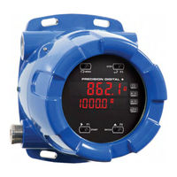
PRECISION DIGITAL ProtEX-MAX PD8-6210 Instruction Manual (64 pages)
Explosion-Proof Analog Input Batch Controller
Brand:
PRECISION DIGITAL
| Category:
Controller
| Size: 3 MB
Table of Contents
Table of Contents
3
Table of Figures
4
Introduction
4
Ordering Information
5
Specifications
6
General
6
Process Input
6
Batch Controller Rate/Totalizer Display
7
Relays
7
Isolated 4-20 Ma Transmitter Output
8
Serial Communications
8
Digital Inputs & Outputs
8
Meterview Pro
8
Product Ratings and Approvals
9
Compliance Information
10
Safety
10
Electromagnetic Compatibility
10
Safety Information
11
Installation
11
Unpacking
11
Figure 1: Transmitter Supply Voltage Selection
12
Pre-Installed Conduit/Stopping Plug
12
Mounting
12
Cover Jam Screw
12
Transmitter Supply Voltage Selection (P+, P-)
12
Figure 2: Integrated Provu Required Connections
13
Connectors Labeling
14
Power Connections
14
Connections
13
Required & Factory Wired Connection
13
Figure 4: Power Connections
14
Figure 3: Connector Labeling for Fully Loaded PD8-6210
14
Figure 5: Transmitters Powered by Internal Supply
15
Figure 7: Voltage Input Connections
15
Figure 6: Transmitter Powered by Ext. Supply or Self-Powered
15
Signal Connections
15
Figure 8: Protex-MAX Connections to a Serial Converter
16
Figure 9. Three-Wire RS485 Connection
16
Figure 12: Relay Connections
19
Figure 13: AC and DC Loads Protection
19
Figure 14: Low Voltage DC Loads Protection
19
Relay Connections
19
Switching Inductive Loads
19
4-20 Ma Output Connections
20
Analog Output Transmitter Power Supply
20
F4 Digital Input Connections
20
Figure 15: F4 Digital Input Connections
20
Figure 16: 4-20 Ma Output Connections
20
Figure 17: Interlock Connection
20
Interlock Relay Feature
20
Digital I/O Connections
21
External Switch Contacts
21
Serial Communications Connections
16
Three Wire Connections
16
Figure 10: RS-485 Wiring
17
Figure 11: RS-485 Two-Wire Multi-Drop Wiring
18
Using PRO V U Serial Adapters
18
Figure 18: Digital I/O Connections
21
Basic Operation and Programming
22
Safetouch ® Buttons
22
Front Buttons and Status LED Indicators
23
Controller Operation
24
Batch Control Operation Example
25
Meterview ® Pro Software
27
Meterview Pro Installation
27
Display Functions and Messages
28
Setting Numeric Values
30
Setting up the Batch Controller (Setup)
31
Scaling and Calibration
32
Setting the Input Signal (Input)
32
Setting the Totalizer and Batching Features (Total)
32
Setting the Input Units or Custom Tags (Units)
32
Setting the Decimal Point (Dec Pt)
32
Programming the Batch Controller (Prog)
33
Input Calibration Method (Incal)
33
Scaling the Controller (SCALE)
34
Time Base, Total Conversion Factor & Total Reset
35
Batch Start Mode (Mode)
35
Calibrating the Controller with External Source (Cal)
35
Setting the Display Parameter & Intensity (Dsplay)
36
Setting the Relay Operation (Relay)
37
Relay Assignment (Assign)
38
Setting the Relay Action
38
Setting Batch Control Relays
38
Programming Alarm Set and Reset Points
39
Setting Fail-Safe Operation
39
Programming Time Delay
39
Relay Action for Loss of 4-20 Ma Input (Loop Break)
39
Relay Operation Details
40
Overview
40
Relays Initialization
40
Fail-Safe Operation
40
Front Panel Leds
40
Automatic Reset (Auto)
41
Pump Alternation Control
41
Setting up the Interlock Relay (Force On) Feature
41
Sample Relay Operation
42
Relay and Alarm Operation Diagrams
42
High Alarm Operation (Set > Reset)
42
Low Alarm Operation (Set < Reset)
42
High Alarm with Fail-Safe Operation (Set > Reset)
42
Low Alarm with Fail-Safe Operation (Set < Reset)
42
Rate Relay Sampling Operation
43
Total Relay Sampling Operation
43
Signal Loss or Loop Break Relay Operation
43
Time Delay Operation
44
Scaling the 4-20 Ma Analog Output (Aout)
44
Reset Menu (Reset)
45
Control Menu (Contrl)
45
Setting up the Password (Pass)
45
Protecting or Locking the Controller
45
Grand Total Reset Password & Non-Resettable Total
46
Making Changes to a Password Protected Controller
46
Disabling Password Protection
46
Advanced Operation and Programming
47
Advanced Features Menu & Display Messages
48
Advanced Setup and Calibration
50
Multi-Point Calibration & Scaling
50
Maximum/Minimum Readings
50
Noise Filter (Filter)
51
Noise Filter Bypass (Bypass)
51
Rounding Feature (Round)
51
Modbus RTU Serial Communications (Serial)
51
F4 Operation
50
Function Keys Operation
50
Figure 19: General Four-Wire Network Connection
52
Figure 20: General Two-Wire Network Connection
52
Serial Communications Overview
52
Select Menu (Select)
53
Signal Conditioning Selection (Functn)
53
Low-Flow Cutoff (Cutoff)
53
Total and Grand Total Count Direction (Count)
54
Analog Output Programming (Aoutpr)
54
Programmable Function Keys User Menu (User)
55
Internal Source Calibration (ICAL)
56
Troubleshooting
57
Diagnostics Menu (Diag)
57
Determining Software Version
57
Reset Controller to Factory Defaults
57
Factory Defaults & User Settings
58
Troubleshooting Tips
59
Service
60
Mounting Dimensions
61
Figure 21: Enclosure Dimensions - Front View
61
Figure 22: Enclosure Dimensions - Side Cross Section View
61
EU Declaration of Conformity
63
Advertisement
Advertisement
Related Products
PRECISION DIGITAL ProtEX-MAX PD8-6310
PRECISION DIGITAL ProtEX-MAX PD8-6310-WM
PRECISION DIGITAL NOVA PD578
PRECISION DIGITAL PD9000 ConsoliDator+
PRECISION DIGITAL PD6310-6R5
PRECISION DIGITAL PD6310-6H4
PRECISION DIGITAL PD6310-6H5
PRECISION DIGITAL PD6310-6H7
PRECISION DIGITAL PD6210-6R2
PRECISION DIGITAL PD6210-7R5
PRECISION DIGITAL Categories
Measuring Instruments
Controller
Monitor
Scanner
Network Hardware
More PRECISION DIGITAL Manuals
Login
Sign In
OR
Sign in with Facebook
Sign in with Google
Upload manual
Upload from disk
Upload from URL