Sign In
Upload
Manuals
Brands
PRECISION DIGITAL Manuals
Measuring Instruments
ProtEX-MAX PD8-6060-7H7
PRECISION DIGITAL ProtEX-MAX PD8-6060-7H7 Manuals
Manuals and User Guides for PRECISION DIGITAL ProtEX-MAX PD8-6060-7H7. We have
1
PRECISION DIGITAL ProtEX-MAX PD8-6060-7H7 manual available for free PDF download: Instruction Manual
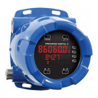
PRECISION DIGITAL ProtEX-MAX PD8-6060-7H7 Instruction Manual (66 pages)
Explosion-Proof Dual-Input Meter
Brand:
PRECISION DIGITAL
| Category:
Measuring Instruments
| Size: 4 MB
Table of Contents
Table of Contents
3
Table of Figures
4
Introduction
4
Ordering Information
5
Specifications
5
General
5
Dual Process Input
6
Relays
7
Isolated 4-20 Ma Transmitter Output
7
Serial Communications
8
Digital Inputs & Outputs
8
Meterview Pro
8
Product Ratings and Approvals
9
Compliance Information
10
Safety
10
Electromagnetic Compatibility
10
Safety Information
11
Installation
11
Unpacking
11
Figure 1. Transmitter Supply Voltage Selection
12
Pre-Installed Conduit/Stopping Plug
12
Mounting
12
Cover Jam Screw
12
Transmitter Supply Voltage Selection (P+, P-)
12
Figure 2: Integrated Provu Required Connections
13
Connectors Labeling
14
Power Connections
14
Connections
13
Required & Factory Wired Connection
13
Figure 4. Power Connections
14
Figure 3. Connector Labeling for Fully Loaded
14
Figure 5. Transmitters Powered by Internal Supply
15
Figure 7. Voltage Input Connections
15
Figure 6. Transmitter Powered by Ext. Supply or Self-Powered
15
Signal Connections
15
Figure 8: Protex-MAX Connections to a Serial Converter
16
Figure 9. Three-Wire RS485 Connection
16
Figure 12. Relay Connections
19
Figure 13. AC and DC Loads Protection
19
Figure 14. Low Voltage DC Loads Protection
19
Relay Connections
19
Switching Inductive Loads
19
4-20 Ma Output Connections
20
Analog Output Transmitter Power Supply
20
F4 Digital Input Connections
20
Figure 15. F4 Digital Input Connections
20
Figure 15. F4 Digital Input Connections
20
Figure 16. 4-20 Ma Output Connections
20
Figure 17. Interlock Connections
20
Interlock Relay Feature
20
Digital I/O Connections
21
External Switch Contacts
21
Serial Communications Connections
16
Three Wire Connections
16
Figure 10: RS-485 Wiring
17
Figure 11: RS-485 Two-Wire Multi-Drop Wiring
18
Using PRO V U Serial Adapters
18
Figure 18: Digital I/O Connections
21
Setup and Programming
22
Overview
22
Safetouch ® Buttons
22
Front Buttons and Status LED Indicators
23
Meterview ® Pro Software
24
Meterview Pro Installation
24
Display Functions & Messages
25
Main Menu
27
Setting Numeric Values
27
Setting up the Meter (Setup)
28
Setting the Input Signal (Input)
28
Setting the Decimal Point (Dec Pt)
29
Programming the Meter (Prog)
29
Meterview ® Pro Software
30
Multi-Point Linearization (Linear)
30
Scaling the Meter for Channel a (Scal-A)
30
Scaling the Meter Without a Signal Source
30
Scaling the Meter for Channel B (Scal-B)
30
Error Message (Error)
31
Calibrating the Meter with External Source
31
Calibrating the Meter for Channel a (CAL-A)
31
Calibrating the Meter for Channel B (CAL-B)
31
Setting the Display Parameter & Intensity (Dsplay)
32
Setting the Input Units or Custom Tags (Units)
33
Setting the Relay Operation (Relay)
34
Setting the Relay Assignment (Assign)
34
Setting the Relay Action
35
Programming Set and Reset Points
35
Setting Fail-Safe Operation
35
Programming Time Delay
35
Relay Action for Loss of 4-20 Ma Input (Loop Break)
35
Relay and Alarm Operation Diagrams
36
High Alarm Operation (Set > Reset)
36
Low Alarm Operation (Set < Reset)
36
High Alarm with Fail-Safe Operation (Set > Reset)
36
Low Alarm with Fail-Safe Operation (Set < Reset)
36
Pump Alternation Control Operation
37
Relay Sampling Operation
37
Signal Loss or Loop Break Relay Operation
38
Time Delay Operation
38
Relay Operation Details
39
Fail-Safe Operation
39
Overview
39
Relays Auto Initialization
39
Front Panel Leds
40
Latching and Non-Latching Relay Operation
40
Latching Relay (Latch)
40
Non-Latching Relay (A-Man)
40
Non-Latching Relay (Auto)
40
Acknowledging Relays
41
Figure 19. Acknowledge Relays W/Function Key or Digital Input
41
Latching Relay (Lt-Clr)
41
Pump Alternation Control Applications (Altern)
42
Setting up the Interlock Relay (Force On) Feature
43
Interlock Relay Operation Example
43
Scaling the 4-20 Ma Analog Output (Aout)
44
Reset Menu (Reset)
44
Control Menu (Contrl)
44
Setting up the Password (Pass)
45
Protecting or Locking the Meter
45
Making Changes to a Password Protected Meter
45
Disabling Password Protection
45
Advanced Features Menu
46
Advanced Features Menu & Display Messages
46
Modbus RTU Serial Communications (Serial)
48
Noise Filter (Filter)
48
Noise Filter Bypass (Bypass)
48
Rounding Feature (Round)
48
Figure 20: General Four-Wire Network Connection
49
Figure 21: General Two-Wire Network Connection
49
Serial Communications Overview
49
Select Menu (Select)
50
Signal Input Conditioning (Functn)
50
Multi-Point Linearization (Linear)
51
Math Constants (Const)
52
Low-Flow Cutoff (Cutoff)
52
Analog Output Programming (Aoutpr)
53
Programmable Function Keys User Menu (User)
53
Tare (Tare A, Tare B)
55
Internal Calibration (ICAL)
55
Math Function (Math)
52
Meter Operation
57
Front Panel Buttons Operation
57
Safetouch ® Buttons
57
F4 Operation
58
Maximum/Minimum Readings
58
Troubleshooting
59
Diagnostics Menu (Diag)
59
Determining Software Version
59
Reset Meter to Factory Defaults
59
Factory Defaults & User Settings
60
Troubleshooting Tips
62
Service
63
Mounting Dimensions
63
Figure 22: Enclosure Dimensions - Front View
63
Figure 23: Enclosure Dimensions - Side Cross Section View
63
EU Declaration of Conformity
65
Advertisement
Advertisement
Related Products
PRECISION DIGITAL ProtEX-MAX PD8-6001 Series
PRECISION DIGITAL ProtEX-MAX PD8-6001-6H0
PRECISION DIGITAL ProtEX-MAX PD8-6001-7H0
PRECISION DIGITAL ProtEX-MAX PD8-6001-7H7
PRECISION DIGITAL ProtEX-MAX PD8-6001-6H7
PRECISION DIGITAL ProtEX-MAX PD8-6060
PRECISION DIGITAL ProtEX-MAX PD8-6060-7H0
PRECISION DIGITAL ProtEX-MAX PD8-6060-6H7
PRECISION DIGITAL ProtEX-MAX PD8-6060-6H0
PRECISION DIGITAL PD8-7000-7H3
PRECISION DIGITAL Categories
Measuring Instruments
Controller
Monitor
Scanner
Test Equipment
More PRECISION DIGITAL Manuals
Login
Sign In
OR
Sign in with Facebook
Sign in with Google
Upload manual
Upload from disk
Upload from URL