Sign In
Upload
Manuals
Brands
PRECISION DIGITAL Manuals
Monitor
PD650-2-34
PRECISION DIGITAL PD650-2-34 Manuals
Manuals and User Guides for PRECISION DIGITAL PD650-2-34. We have
1
PRECISION DIGITAL PD650-2-34 manual available for free PDF download: Instruction Manual
PRECISION DIGITAL PD650-2-34 Instruction Manual (96 pages)
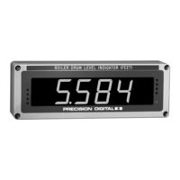
PD650 series. Large Display Process Meter With Rate/Totalizer/Batch Control Features
Brand:
PRECISION DIGITAL
| Category:
Monitor
| Size: 1 MB
Table of Contents
Table of Contents
3
Introduction
7
Features
7
Typical Applications
8
Ordering Information
8
Safety Notice
9
Specifications
10
Basic Process Meter
10
Rate/Totalizer/Batch Controller Features
11
Options
12
Display Functions and Messages
15
Setup and Programming
17
Overview
17
List of Figures
18
Figure 1. Removing the Display Board
18
Disassembling the Meter
18
Reassembling the Meter
18
Jumper Configuration
19
Overview
19
Jumper Arrays Function and Location
19
Figure 2. Input Power Label
20
Power Selection
20
Changing from 115 to 230 VAC Power
20
Labeling Meter for 115 VAC, 230 VAC, or 24 VDC
20
Overview
20
Figure 3. Connections and Jumper Diagram
21
Wiring Instructions
22
Connections
21
Overview
21
Figure 4. Options Board Connectors and J5 Jumper
22
Power Connections
23
Terminals Designation
22
Figure 5. Input Power Connections
23
Figure 6. Two-Wire Transmitter Powered by Meter
24
Figure 7. Two-Wire Transmitter Powered by External Supply
24
Figure 8. Three-Wire Transducer Powered by Meter
25
Figure 9. Direct Voltage Signal Connections
25
Figure 10. External Control Connections
26
Figure 11. Relay and 4-20 Ma Output Terminals
26
Isolated 4-20 Ma Output Option Connections
27
Signal Connections
24
Enter, Acknowledgement, and Reset Total Connections
26
Optional Relays & 4-20 Ma Output Terminals
26
Figure 12. both Input and Output Loops Powered by Meter
27
Figure 13. Input Loop Powered by Meter, Output Loop Powered from External Supply
27
Programming
28
General Programming Description
28
ENTER and ACK Functionality
28
Overview
28
Figure 14. Jumper Arrays and Status LED Identification
29
Figure 15. Two-Point Calibration Flowchart
31
Figure 16. JP1 Input Signal Selection Array
32
Initial Calibration with External Source (if Needed)
33
Select Calibration Method
33
Scale or Calibrate the Meter
34
Scale Using Internal Calibration (I-CAL)
34
Minimum Input Span (Error Message)
35
Calibrate Using External Calibration (E-CAL)
38
Calibration Error (Error)
40
Round Horizontal Tank Calibration Points
40
Model PD650 Large Display Process Meter Instruction Manual
41
Overview
41
Rate Meter Programming
41
Set Display to Rate (Dspy R)
41
Low-Flow Cutoff Programming (Cutoff)
42
Overview
43
Set Display for Total (Dspy T)
43
Totalizer Programming
43
Set Rate Time Base (T Base)
44
Set Totalizer Conversion Factor (Tot CF)
44
Set Totalizer Decimal Point (Tot Dp)
45
Parameter Combinations Resulting in Error Message (Error1 )
46
Set Alternating Total/Rate Display
46
Overview
47
Set Point Setup and Programming
47
Set Relays for Fail-Safe Operation
48
Set Relays for Manual or Automatic Reset
48
Assigning Set Points to Process/Rate or Total (Setup)
49
Rate or Total, Latching or Non-Latching Relays
50
Programming Internal Total Reset and Delay (Delay)
52
Setting Relays for Pump Alternation (Altern)
53
Overview
54
Preset Offset Values for Total Set Points (OFFSET)
54
Preset Values for Total Set Points
54
Programming Alarm Points and Presets (Setpts)
54
Set and Reset Points for Process/Rate Alarms
54
Programming Alarm and Preset Values (Setpts)
55
Basic Meter Programming
32
Overview
32
Select Input Signal
32
Five Basic Digit/Display Setting Instructions
30
Figure 18. Display Showing Location of Set, Reset and Rate Leds
55
Figure 19. Programming Status of Set Point Leds Assigned to Total
56
Figure 20. Functions Locked out with the Lockout Jumper
60
Figure 21. Menu Titles Excluded with Display Menu
61
Alternating Display
62
Include or Exclude Menu Titles from Menu Scroll
63
Display Selection (Dsplay)
61
Figure 17. Display Showing Location of Set Point Leds
55
Ma Isolated Output Option Programming (Output)
59
4-20 Ma Output Programming Confirmation
59
Lockout and Display Selection Programming
60
Overview
60
Lockout
60
Figure 22. Front Panel Leds
64
Operation
64
Overview
64
Figure 23. Meter Displaying Process/Rate
65
Figure 24. Meter Displaying Total
65
Two Types of Display: Process/Rate and Total
65
Basic Meter Operation
66
Overview
66
ENTER and ACK Button Operation
66
Display Peak & Reset Peak Operation (Dspy P & Rset P)
67
Rate Meter Operation
68
Overview
68
Display Rate (Dspy R)
68
Low-Flow Cutoff (Cutoff)
68
Totalizer Operation
69
Overview
69
Display Total (Dspy T)
69
Total Conversion Factor (Tot CF) & Time Base (T Base)
69
Applications Using Total Conversion Factor and Time Base
70
Resetting Total Automatically Via User Selectable Preset
71
Resetting Total Using the ENTER Button
71
Resetting Total Via External Contact Closure
71
Totalizer Reset
71
Relays Operation
72
Fail-Safe Operation
72
Overview
72
Relays Auto Initialization
72
Figure 25. Front Panel LED Indicator Locations
73
Front Panel Leds
73
Acknowledging Relays
75
Simple On/Off Control with 100% Deadband Operation
76
Manual Batch Control Operation
78
Automatic Batch Control Operation
79
Delay on Release (Delay)
80
Batch Control with Varying Batch Sizes
80
Priority Batch Programming or Quick Presets
80
Pump Alternation Control
81
Pump Alternation Typical Application
81
Switching Inductive Loads
82
AC and DC Loads
82
Low Voltage DC Loads
82
Figure 26. AC and DC Loads Protection
82
Figure 27. Low Voltage DC Loads Protection
82
4-20 Ma Output Operation
83
Overview
83
Lockout and Display Selection Operation
83
Low Voltage Detector
83
Installation
84
Wall Mounting Dimensions
84
Figure 28. Overall Dimensions
84
Figure 29. Wall Mounting Dimensions
84
Panel Mounting Instructions
85
Figure 30. Panel Mounting Instructions
85
Figure 31. Panel Mounting Cutout
85
Option Card Removal & Installation
87
Figure 32. Removing the Display Board
87
Figure 33. Options Board Installation
87
Figure 34. Options Board Installed
88
Programmed Parameter Settings
89
Diagnostic Feature ( Dia9 )
93
Overview
93
Operation
93
Other Precision Digital Products
94
Advertisement
Advertisement
Related Products
PRECISION DIGITAL PD650-2-N
PRECISION DIGITAL PD650-2-35
PRECISION DIGITAL PD650-2-36
PRECISION DIGITAL PD650-2-37
PRECISION DIGITAL PD650-2-38
PRECISION DIGITAL PD650-N
PRECISION DIGITAL PD650-36
PRECISION DIGITAL PD650-34
PRECISION DIGITAL PD650-37
PRECISION DIGITAL PD650-35
PRECISION DIGITAL Categories
Measuring Instruments
Controller
Monitor
Scanner
Test Equipment
More PRECISION DIGITAL Manuals
Login
Sign In
OR
Sign in with Facebook
Sign in with Google
Upload manual
Upload from disk
Upload from URL