Sign In
Upload
Manuals
Brands
PRECISION DIGITAL Manuals
Controller
PD6210-7H7
PRECISION DIGITAL PD6210-7H7 Manuals
Manuals and User Guides for PRECISION DIGITAL PD6210-7H7. We have
1
PRECISION DIGITAL PD6210-7H7 manual available for free PDF download: Instruction Manual
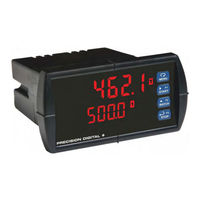
PRECISION DIGITAL PD6210-7H7 Instruction Manual (56 pages)
Analog Input Batch ControlleR
Brand:
PRECISION DIGITAL
| Category:
Controller
| Size: 2 MB
Table of Contents
Table of Contents
3
Table of Figures
4
Introduction
4
Ordering Information
5
Specifications
6
General
6
Process Input
6
Batch Controller Rate/Totalizer Display
7
Relays
7
Isolated 4-20 Ma Transmitter Output
8
Modbus ® RTU Serial Communications
8
PDA1044 Digital Input & Output Expansion Module
8
Meterview Pro
8
Compliance Information
9
Safety
9
Electromagnetic Compatibility
9
Safety Information
10
Installation
10
Unpacking
10
Panel Mounting Instructions
10
Figure 1: 1/8 DIN Panel Mounting
10
Mounting Dimensions
11
Transmitter Supply Voltage Selection (P+, P-)
11
Figure 2: Controller Dimensions - Side View
11
Figure 3: Controller Dimensions - Top View
11
Figure 4: Transmitter Supply Voltage Selection
11
Connections
12
Connectors Labeling
12
Power Connections
12
Figure 5: Connector Labeling for Fully Loaded
12
Figure 6: Power Connections
12
Signal Connections
13
Figure 7: Transmitters Powered by Internal Supply
13
Figure 8: Transmitter Powered by Ext. Supply or Self-Powered
13
Figure 9: Voltage Input Connections
13
Modbus RTU Serial Communications
14
Relay Connections
14
Switching Inductive Loads
14
Figure 10: Relay Connections
14
Figure 11: AC and DC Loads Protection
14
Figure 12: Low Voltage DC Loads Protection
14
F4 Digital Input Connections
15
4-20 Ma Output Connections
15
Analog Output Transmitter Power Supply
15
Figure 13: F4 Digital Input Connections
15
Figure 14: 4-20 Ma Output Connections
15
External Relay & Digital I/O Connections
16
Interlock Relay Feature
16
Figure 15: Expansion Modules & DIN Rail Mounting Kit
16
Figure 16: External Relays Module Connections
16
Figure 17: Digital I/O Module Connections
16
Figure 18: Interlock Connection
16
Basic Operation and Programming
17
Front Panel Buttons and Status LED Indicators
17
Controller Operation
18
Batch Control Operation Example
19
Meterview ® Pro Software
21
Meterview Pro Installation
21
Display Functions and Messages
22
Setting Numeric Values
24
Setting up the Batch Controller (Setup)
25
Scaling and Calibration
26
Setting the Input Signal (Input)
26
Setting the Totalizer and Batching Features (Total)
26
Setting the Input Units or Custom Tags (Units)
26
Setting the Decimal Point (Dec Pt)
26
Programming the Batch Controller (Prog)
27
Batch Start Mode (Mode)
29
Setting the Display Parameter & Intensity (Dsplay)
30
Setting the Relay Operation (Relay)
31
Relay Assignment (Assign)
32
Setting the Relay Action
32
Setting Batch Control Relays
32
Programming Alarm Set and Reset Points
33
Setting Fail-Safe Operation
33
Programming Time Delay
33
Relay Action for Loss of 4-20 Ma Input (Loop Break)
33
Relay Operation Details
34
Overview
34
Relays Initialization
34
Fail-Safe Operation
34
Front Panel Leds
34
Automatic Reset (Auto)
35
Pump Alternation Control
35
Setting up the Interlock Relay (Force On) Feature
35
Sample Relay Operation
36
Relay and Alarm Operation Diagrams
36
High Alarm Operation (Set > Reset)
36
Low Alarm Operation (Set < Reset)
36
High Alarm with Fail-Safe Operation (Set > Reset)
36
Low Alarm with Fail-Safe Operation (Set < Reset)
36
Rate Relay Sampling Operation
37
Total Relay Sampling Operation
37
Signal Loss or Loop Break Relay Operation
37
Time Delay Operation
38
Scaling the 4-20 Ma Analog Output (Aout)
38
Reset Menu (Reset)
39
Control Menu (Contrl)
39
Setting up the Password (Pass)
39
Protecting or Locking the Controller
39
Grand Total Reset Password & Non-Resettable Total
40
Making Changes to a Password Protected Controller
40
Disabling Password Protection
40
Advanced Operation and Programming
41
Advanced Features Menu & Display Messages
42
Function Keys Operation
44
F4 Operation
44
Advanced Setup and Calibration
44
Maximum/Minimum Readings
44
Noise Filter (Filter)
45
Noise Filter Bypass (Bypass)
45
Rounding Feature (Round)
45
Modbus RTU Serial Communications (Serial)
45
Select Menu (Select)
46
Programmable Function Keys User Menu (User)
47
Internal Source Calibration (ICAL)
49
Troubleshooting
50
Diagnostics Menu (Diag)
50
Determining Software Version
50
Reset Controller to Factory Defaults
50
Factory Defaults & User Settings
51
Troubleshooting Tips
53
EU Declaration of Conformity
55
Advertisement
Advertisement
Related Products
PRECISION DIGITAL PD6210-7R2
PRECISION DIGITAL PD6210-7R4
PRECISION DIGITAL PD6210-7R5
PRECISION DIGITAL PD6210-7R7
PRECISION DIGITAL PD6210-7H2
PRECISION DIGITAL PD6210-7H4
PRECISION DIGITAL PD6210-7H5
PRECISION DIGITAL PD6210-6R2
PRECISION DIGITAL PD6210-6R5
PRECISION DIGITAL PD6210-6H4
PRECISION DIGITAL Categories
Measuring Instruments
Controller
Monitor
Scanner
Network Hardware
More PRECISION DIGITAL Manuals
Login
Sign In
OR
Sign in with Facebook
Sign in with Google
Upload manual
Upload from disk
Upload from URL