Precision Digital Corporation PROVU PD6262-6R7 Manuals
Manuals and User Guides for Precision Digital Corporation PROVU PD6262-6R7. We have 2 Precision Digital Corporation PROVU PD6262-6R7 manuals available for free PDF download: Instruction Manual

Precision Digital Corporation PROVU PD6262-6R7 Instruction Manual (104 pages)
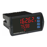
Analog Dual-Input Rate/Totalizer
Brand: Precision Digital Corporation
|
Category: Measuring Instruments
|
Size: 1 MB
Table of Contents
Advertisement
Precision Digital Corporation PROVU PD6262-6R7 Instruction Manual (54 pages)
Dual Analog Input Rate/Totalizer
Brand: Precision Digital Corporation
|
Category: Monitor
|
Size: 4 MB
Table of Contents
Advertisement
Related Products
- Precision Digital Corporation PROVU PD6262-6R0
- Precision Digital Corporation PROVU PD6262-6R2
- Precision Digital Corporation PROVU PD6262-6R3
- Precision Digital Corporation PROVU PD6262-6R4
- Precision Digital Corporation PROVU PD6262-6R5
- Precision Digital Corporation PROVU PD6262-6H3
- Precision Digital Corporation PROVU PD6262-6H4
- Precision Digital Corporation PROVU PD6262-6H5
- Precision Digital Corporation PROVU PD6262-6H7
- Precision Digital Corporation PROVU PD6262-6H2