Sign In
Upload
Manuals
Brands
Precision Digital Corporation Manuals
Media Converter
PDA8232-N
Precision Digital Corporation PDA8232-N Manuals
Manuals and User Guides for Precision Digital Corporation PDA8232-N. We have
3
Precision Digital Corporation PDA8232-N manuals available for free PDF download: Instruction Manual
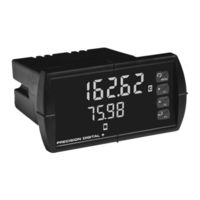
Precision Digital Corporation PDA8232-N Instruction Manual (104 pages)
Analog Dual-Input Rate/Totalizer
Brand:
Precision Digital Corporation
| Category:
Measuring Instruments
| Size: 1 MB
Table of Contents
Table of Contents
3
Introduction
6
Ordering Information
7
Specifications
8
General
8
Dual Process Input
10
Dual Rate/Totalizer
12
Relays
13
Isolated 4-20 Ma Transmitter Output
14
Modbus® RTU Serial Communications
14
Compliance Information
15
Safety
15
Electromagnetic Compatibility
15
Safety Information
16
Installation
16
Unpacking
16
Panel Mounting Instructions
16
Figure 1. 1/8 DIN Panel Cutout Dimensions
17
Figure 2. Panel Mounting Details
17
Figure 3. Meter Dimensions - Side View
18
Figure 4. Meter Dimensions - Top View
18
Mounting Dimensions
18
Figure 5. Jumper Configuration for 12/24 VDC Power
19
Configuration for 12 or 24 VDC Power Option
19
Figure 6. Transmitter Supply Voltage Selection
20
Connectors Labeling
21
Power Connections
21
Transmitter Supply Voltage Selection (P+, P-)
20
Connections
20
Figure 8. Power Connections
21
Figure 7. Connector Labeling for Fully Loaded PD6262
21
Figure 10. Transmitter Powered by Ext. Supply or Self-Powered
22
Figure 9. Transmitters Powered by Internal Supply
22
Figure 11. Voltage Input Connections
23
Figure 12. Relay Connections
23
Modbus RTU Serial Communications
23
Relay Connections
23
Figure 13. AC and DC Loads Protection
24
Figure 14. Low Voltage DC Loads Protection
24
Switching Inductive Loads
24
4-20 Ma Output Connections
25
Analog Output Transmitter Power Supply
25
F4 Digital Input Connections
25
Figure 15. F4 Digital Input Connections
25
Figure 16. 4-20 Ma Output Connections
25
External Relay, Analog Output, & Digital I/O Connections
26
Interlock Relay Feature
26
Signal Connections
22
Figure 17. Interlock Connections
26
Setup and Programming
27
Front Panel Buttons and Status LED Indicators
28
Display Functions & Messages
29
Main Menu
35
Setting Numeric Values
36
Model PD6262 Analog Dual-Input Rate/Totalizer Instruction Manual
37
Setting up the Meter (Setup)
37
Setting the Input Signal (Input)
38
Setting the Totalizer Features (Total)
38
Setting the Rate, Total, & Grand Total Units/Tags (Units)
39
Setting the Decimal Point (Dec Pt)
40
Programming the Rate/Totalizer (Prog)
41
Input Calibration Method (Incal)
42
Scaling the Meter Without a Signal Source (SCAL-A, SCAL-B)
43
Calibrating the Meter with External Source
44
Error Message (Error)
44
Total & Grand Total Reset
46
Total and Grand Total Setup
46
Setting the Display Parameters & Intensity (Dsplay)
47
Display Setup Menu
48
Setting the Relay Operation (Relay)
49
Setting the Relay Assignment (Assign)
50
Setting the Relay Action (Act)
51
Programming Set and Reset Points
52
Programming Time Delay
52
Relay Action for Loss of 4-20 Ma Input (Loop Break)
52
Setting Fail-Safe Operation
52
Relay and Alarm Operation Diagrams
53
High Alarm Operation (Set > Reset)
53
Low Alarm Operation (Set < Reset)
54
High Alarm with Fail-Safe Operation (Set > Reset)
55
Low Alarm with Fail-Safe Operation (Set < Reset)
56
Pump Alternation Control Operation
57
Relay Sampling Operation
58
Total Relay Sampling Operation
58
Signal Loss or Loop Break Relay Operation
59
Time Delay Operation
60
Relay Operation Details
61
Overview
61
Relays Auto Initialization
61
Fail-Safe Operation
61
Front Panel Leds
62
Latching and Non-Latching Relay Operation
62
Non-Latching Relay (Auto)
63
Non-Latching Relay (A-Man)
63
Latching Relay (Latch)
63
Latching Relay (Lt-Clr)
64
Acknowledging Relays
64
Figure 18. Acknowledge Relays W/Function Key or Digital Input
64
Model PD6262 Analog Dual-Input Rate/Totalizer Instruction Manual
66
Setting up the Interlock Relay (Force On) Feature
66
Scaling the 4-20 Ma Analog Output (Aout)
66
Reset Menu (Reset)
67
Control Menu (Contrl)
67
Setting up the Password (Pass)
67
Protecting or Locking the Meter Functions
68
Total Reset Password & Non-Resettable Total
68
Making Changes to a Password Protected Meter
69
Disabling Password Protection
69
Advanced Features Menu
70
Advanced Features Menu & Display Messages
71
Noise Filter (Filter)
75
Noise Filter Bypass (Bypass)
75
Rounding Feature (Round)
75
Modbus RTU Serial Communications (Serial)
75
Select Menu (Select)
76
Signal Input Conditioning (Functn)
77
Square Root Linearization (Square)
77
Programmable Exponent Linearization (Prog E)
77
Multi-Point Linearization (Linear)
78
Math Function (Nmath)
79
Math Constants (Const)
80
Low-Flow Cutoff (Cutoff)
80
Totalizer Count Up/Down (Count)
81
Analog Output Programming (Aoutpr)
81
Programmable Function Keys User Menu (User)
83
Internal Calibration (ICAL)
84
Meter Copy Function (Copy)
86
Meter Operation
88
Front Panel Buttons Operation
88
Function Keys Operation
89
F4 Operation
89
Maximum/Minimum Readings
89
Troubleshooting
90
Diagnostics Menu (Diag)
90
Determining Software Version
90
Reset Meter to Factory Defaults
91
Factory Defaults & User Settings
92
Alphabetical List of Display Functions & Messages
96
Troubleshooting Tips
103
Advertisement
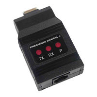
Precision Digital Corporation PDA8232-N Instruction Manual (19 pages)
Serial Communication Converters & Adapters
Brand:
Precision Digital Corporation
| Category:
Media Converter
| Size: 1 MB
Table of Contents
Introduction
2
Ordering Information
2
Table of Contents
3
Specifications
5
PDA1232 PRO V URS-232 Adapter
5
PDA1485 PRO V URS-485 Adapter
5
PDA7232 Trident RS-232 Adapter
5
PDA7420 Trident Meter Copy Cable
5
PDA7422 Trident RS-485 Adapter
5
PDA7485 RS-232 to RS-485 Converter
5
PDA8006 Trident USB Adapter
6
PDA8008 PRO VU UUSB Adapter
6
PDA8232 USB to RS-232 Converter
6
PDA8485 USB to RS-485 Converter
6
General (All)
6
USB Drivers for Serial Communications Adapters
6
Figure 1. DIN Rail Clips Mounted to Expansion Module
7
Figure 2. Hinge & Latch End of DIN Rail Clip
7
Figure 3. DIN Rail Clips Mounted to Module
7
Figure 4. Examples of Clips Mounted to Modules
7
Figure 5. Mounting the DIN Rail with 2 #10 Pan Head Screws
7
Figure 6. Examples of Modules Mounted to DIN Rail
7
Figure 7. Snapping the Module to the DIN Rail
7
Figure 8. Typical Installation of DIN Rail Mounted Devices
7
DIN Rail Mounting Instructions
7
Figure 9. General Four-Wire Network Connections
8
Figure 10. General Two-Wire Network Connections
8
Serial Communications Overview
8
PDA1232 PRO VU URS-232 Serial Adapter
9
Description
9
Installation
9
Connections
9
Figure 11. RS-232 Adapter Connections
9
PDA1485 PRO VU URS-485 Serial Adapter
10
Description
10
Installation
10
Connections
10
Figure 12. RS-422 or RS-485 Wiring
10
Figure 13. RS-485 Two-Wire Multi-Drop Wiring
10
Figure 14. Connections for PDA1485 to Serial Converter
10
PDA7232 Trident RS-232 Serial Adapter
11
Description
11
Installation
11
Connections
11
PDA7420 Trident Meter Copy Cable
11
Operation
11
Figure 15. RS-232 Adapter Connections
11
Figure 16. Standard Modular Cable Wiring
11
Figure 17. Trident Copy Cable Connecting Two Meters
11
PDA7422 Trident RS-485 Serial Adapter
12
Description
12
Installation
12
Figure 18. RS-422 or RS-485 Wiring
12
Figure 19. RS-485 Two-Wire Multi-Drop Wiring
12
Connections
13
PDA7485 RS-232 to RS-485 Converter
13
Description
13
Installation
13
Figure 20. Standard Modular Cable Wiring
13
Figure 21. Connections for PDA7422 to Serial Converter
13
Figure 22. PDA7485 Connections and DIP Switch Settings
13
Connections
14
Figure 23. PDA7485 DIP Switch Settings Chart
14
Figure 24. PDA7485 RS-485 Two-Wire Multi-Drop Wiring
14
Figure 25. Connections for PDA7485 in a Four-Wire Network
14
Figure 26. Connections for PDA7485 in a Two-Wire Network
14
PDA8006 Trident to USB Serial Adapter
15
Description
15
Installation
15
USB Drivers for PDA8006
15
Pda8008 Pro Vu
15
Figure 27. Trident USB Adapter Connections
15
Figure 28. PRO V UUSB Adapter Connections
15
USB Drivers for PDA8008
15
Figure 29. Connections for PDA8232 to Serial Device
16
Figure 30. PDA8485 DIP Switch Location
16
Connections
17
Figure 31. PDA8485 DIP Switch Settings
17
Figure 32. Connections for PDA8485 in a Four-Wire Network
17
Figure 33. Connections for PDA8485 in a Two-Wire Network
17
Figure 34. PDA8485 RS-485 Two-Wire Multi-Drop Wiring
17
PDA8232 USB to RS-232 Converter
16
Description
16
Installation
16
PDA8485 USB RS-485 Converter
16
Troubleshooting
18
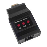
Precision Digital Corporation PDA8232-N Instruction Manual (20 pages)
Serial Communication Converters & Adapters
Brand:
Precision Digital Corporation
| Category:
Media Converter
| Size: 3 MB
Table of Contents
Safety Information
2
Ordering Information
2
Table of Contents
3
Table of Figures
3
Specifications
4
PDA1232 PRO RS-232 Serial Adapter
4
PDA1485 PRO V URS-485 Serial Adapter
4
PDA7232 Trident RS-232 Serial Adapter
4
PDA7422 Trident RS-485 Serial Adapter
4
PDA7485 RS-232 to RS-422/485 Converter
5
PDA8006 Trident USB Serial Adapter
5
PDA8232 USB to RS-232 Converter
5
PDA8485 USB to RS-422/485 Converter
5
Serial Communications Overview
6
Figure 1. General Four-Wire Network Connection
6
Figure 2. General Two-Wire Network Connection
6
PDA1232 PRO VU URS-232 Serial Adapter
7
Description
7
Installation
7
Connections
7
PRO V U Serial Communication Address (Serial)7
7
Pro Vu
7
Figure 3. RS-232 Adapter Connections
7
Description
8
Installation
8
Figure 4. RS-422 or RS-485 Wiring
8
Connections
9
Figure 5. RS-485 Two-Wire Multi-Drop Wiring
9
Figure 6. Connections for PDA1485 to Serial
9
Converter
9
PDA7232 Trident RS-232 Serial Adapter
10
Description
10
Installation
10
Connections
10
Figure 7. RS-232 Adapter Connections
10
Figure 8. Standard Modular Cable Wiring
10
PDA7422 Trident RS-485 Serial Adapter
11
Description
11
Installation
11
PD765 Serial Communication Address (Serl)
11
Figure 9. RS-422 or RS-485 Wiring
11
Connections
12
Figure 10. RS-485 Two-Wire Multi-Drop Wiring
12
Figure 11. Standard Modular Cable Wiring
12
Figure 12. Connections for PDA7422 to Serial Converter
12
PDA7485 RS-232 to RS-422/485 Converter
13
Description
13
Installation
13
Figure 13. PDA7485 Terminal Connectors and DIP Switch
13
Figure 14. PDA7485 DIP Switch Settings
13
Connections
14
Figure 15. RS-485 Two-Wire Multi-Drop Wiring
14
Figure 16. Connections for PDA7485 in a Four-Wire Network
14
Figure 17. Connections for PDA7485 in a Two-Wire Network
14
PDA8006 Trident to USB Serial Adapter
15
Description
15
Installation
15
Figure 18. USB Adapter Connections
15
PDA8232 USB to RS-232 Converter
16
Description
16
Installation
16
PDA8485 USB to RS-422/485 Converter
17
Description
17
Installation
17
Connections
18
Troubleshooting
19
Advertisement
Advertisement
Related Products
Precision Digital Corporation PROVU PDA8008
Precision Digital Corporation PDA8232
Precision Digital Corporation PDA8485
Precision Digital Corporation PDA8006
Precision Digital Corporation PDA8485-I
Precision Digital Corporation PDA1500 Series
Precision Digital Corporation PDA1500-115
Precision Digital Corporation PROVU PDA1232
Precision Digital Corporation PROVU PDA1485
Precision Digital Corporation PDA7422
Precision Digital Corporation Categories
Measuring Instruments
Controller
Cash Counter
Scanner
Racks & Stands
More Precision Digital Corporation Manuals
Login
Sign In
OR
Sign in with Facebook
Sign in with Google
Upload manual
Upload from disk
Upload from URL