Sign In
Upload
Manuals
Brands
Precision Digital Corporation Manuals
Measuring Instruments
Helios PD2-6001
Precision Digital Corporation Helios PD2-6001 Manuals
Manuals and User Guides for Precision Digital Corporation Helios PD2-6001. We have
2
Precision Digital Corporation Helios PD2-6001 manuals available for free PDF download: Instruction Manual
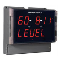
Precision Digital Corporation Helios PD2-6001 Instruction Manual (58 pages)
Large Display Feet & Inches Meter
Brand:
Precision Digital Corporation
| Category:
Measuring Instruments
| Size: 3 MB
Table of Contents
Table of Contents
3
Table of Figures
4
Introduction
4
Ordering Information
4
Specifications
5
General
5
Process Input
5
Relays
6
Isolated 4-20 Ma Transmitter Output
6
RS485 Serial Communications Terminal
6
Modbus ® RTU Serial Communications
6
Digital Input & Output Terminal
7
Compliance Information
7
Safety
7
Safety Information
8
Installation
8
Unpacking
8
Wall Mounting Instructions
9
Mounting Dimensions
9
Figure 1. Meter Mounting Holes
9
Figure 2. Meter Dimensions - Side View
9
Figure 3. Meter Dimensions - Front View
9
Pipe Mounting Instructions
10
Figure 4. Vertical Pipe Mount Assembly
10
Figure 5. Horizontal Pipe Mount Assembly
10
Transmitter Supply Voltage Selection (P+, P-)
11
Connections
11
Figure 6. Transmitter Supply Voltage Selection
11
Connectors Labeling
12
Power Connections
12
Figure 7. Connector Labeling for Fully Loaded PD2-6001
12
Figure 8. Power Connections
12
Signal Connections
13
Figure 9. Transmitters Powered by Internal Supply
13
Figure 10. Transmitter Powered by Ext. Supply or Self
13
Modbus RTU Serial Communications
14
Relay Connections
14
Figure 11. Voltage Input Connections
14
Figure 12. Relay Connections
14
Switching Inductive Loads
15
Figure 13. AC and DC Loads Protection
15
Figure 14. Low Voltage DC Loads Protection
15
RS485 Output Connections
16
Figure 15. RS-422 or RS-485 Wiring
16
Figure 16. RS-485 Two-Wire Multi-Drop Wiring
17
Figure 17. Connections for RS485 Connector to Serial
17
Digital I/O Connections
18
F4 Digital Input Connections
18
Figure 18. Three-Wire RS485 Connection
18
Figure 19. Digital Input and Output Connections
18
Figure 20. F4 Digital Input Connections
18
4-20 Ma Output Connections
19
Analog Output Transmitter Power Supply
19
Interlock Relay Feature
19
Figure 21. 4-20 Ma Output Connections
19
Figure 22. Interlock Connections
19
Setup and Programming
20
Overview
20
Programming Buttons and Status LED Indicators
21
Meterview ® Pro Software
22
Meterview Pro Installation
22
Display Functions & Messages
23
Main Menu
25
Setting Numeric Values
25
Setting up the Meter (Setup)
26
Setting the Input Signal (Input)
27
Setting the Input Units or Custom Tags (Units)
27
Setting the Decimal Point (Dec Pt)
28
Programming the Meter (Prog)
28
Setting the Display Parameter & Intensity (Dsplay)
31
Setting the Relay Operation (Relay)
32
Setting the Relay Action
33
Programming Set and Reset Points
33
Setting Fail-Safe Operation
33
Programming Time Delay
33
Relay Action for Loss of 4-20 Ma Input (Loop Break)
34
Relay and Alarm Operation Diagrams
34
High Alarm Operation (Set > Reset)
34
Low Alarm Operation (Set < Reset)
34
High Alarm with Fail-Safe Operation (Set > Reset)35
35
Low Alarm with Fail-Safe Operation (Set < Reset)
35
Pump Alternation Control Operation
35
Relay Sampling Operation
36
Signal Loss or Loop Break Relay Operation
36
Time Delay Operation
36
Relay Operation Details
37
Overview
37
Relays Auto Initialization
37
Fail-Safe Operation
37
Front Panel Leds
37
Latching and Non-Latching Relay Operation
38
Non-Latching Relay (Auto)
38
Non-Latching Relay (A-Man)
38
Latching Relay (Latch)
38
Latching Relay (Lt-Clr)
38
Acknowledging Relays
39
Pump Alternation Control Applications (Altern)
39
Figure 23. Acknowledge Relays W/Function Key or Digital Input
39
Setting up the Interlock Relay (Force On) Feature
41
Scaling the 4-20 Ma Analog Output (Aout)
42
Reset Menu (Reset)
42
Control Menu (Contrl)
42
Setting up the Password (Pass)
43
Protecting or Locking the Meter
43
Making Changes to a Password Protected Meter
44
Disabling Password Protection
44
Advanced Features Menu
45
Advanced Features Menu & Display Messages
45
Noise Filter (Filter)
47
Noise Filter Bypass (Bypass)
47
Rounding Feature (Round)
47
Modbus RTU Serial Communications (Serial)
48
Select Menu (Select)
49
Signal Input Conditioning (Functn)
49
Low-Flow Cutoff (Cutoff)
51
Analog Output Programming (Aoutpr)
51
Programmable Function Keys User Menu (User)
51
Tare (Tare)
52
Internal Source Calibration (ICAL)
53
Meter Operation
54
Button Operation
54
Function Key Operation
54
Digital Input Operation
54
Maximum/Minimum Readings
55
Troubleshooting
55
Diagnostics Menu (Diag)
55
Determining Software Version
56
Reset Meter to Factory Defaults
56
Factory Defaults & User Settings
57
Troubleshooting Tips
58
Advertisement
Precision Digital Corporation Helios PD2-6001 Instruction Manual (52 pages)
Analog Input Feet & Inches Meter
Brand:
Precision Digital Corporation
| Category:
Measuring Instruments
| Size: 3 MB
Table of Contents
Table of Contents
3
Introduction
6
Ordering Information
6
Specifications
9
General
9
Process Input
10
Relays
10
USB Connection
10
Isolated 4-20 Ma Transmitter Output
11
RS-485 Serial Communications
11
Modbus ® RTU Serial Communications
11
Digital Input (F4)
11
Digital Inputs & Outputs
11
Meterview Pro Software
11
Compliance Information
12
Safety
12
Safety Information
12
Installation
12
Unpacking
12
Wall Mounting Instructions
13
Mounting Dimensions
13
Conduit Holes Location
13
Pipe Mounting Instructions
14
Installation Overview
15
Meterview Pro Software
15
Meterview Pro Installation
15
Transmitter Supply Voltage Selection (P+, P-)
16
Connections
17
Connectors Labeling
17
Power Connections
18
Signal Connections
18
Relay Connections
18
Switching Inductive Loads
19
RS-485 Connections
19
RS-485 Multi-Drop Connection
19
RS-485 Serial Converters
19
Digital I/O Connections
20
F4 Digital Input Connections
21
4-20 Ma Output Connections
21
Analog Output Power Supply
21
Remote Operation of Meter
21
Interlock Relay Feature
21
Setup and Programming
22
Overview
22
LED Status Indicators
22
Programming Buttons
23
Display Functions & Messages
24
Main Menu
25
Setting Numeric Values
26
Setting up the Meter (Setup)
26
Setting the Input Signal (Input)
27
Setting the Input Units or Custom Tags (Units)
27
Setting the Decimal Point (Dec Pt)
28
Programming the Meter (Prog)
28
Setting the Display Parameter & Intensity (Dsplay)
30
Display Intensity (D-Inty)
30
Setting the Relay Operation (Relay)
31
Setting the Relay Action
31
Programming Set and Reset Points
32
Setting Fail-Safe Operation
32
Programming Time Delay
32
Relay Action for Loss of 4-20 Ma Input (Loop Break)
32
Relay and Alarm Operation Diagrams
32
High Alarm Operation (Set > Reset)
32
Low Alarm Operation (Set < Reset)
33
High Alarm with Fail-Safe Operation (Set > Reset)
33
Low Alarm with Fail-Safe Operation (Set < Reset)
33
Time Delay Operation
33
Pump Alternation Control Operation
34
Relay Sampling Operation
34
Relay Operation Details
35
Overview
35
Relays Auto Initialization
35
Fail-Safe Operation
35
Front Panel Leds
35
Latching and Non-Latching Relay Operation
35
Non-Latching Relay (Auto)
36
Non-Latching Relay with Manual Reset (A-Nman)
36
Latching Relay (Latch)
36
Latching Relay with Clear (Lt-Clr)
36
Acknowledging Relays
37
Pump Alternation Control Applications (Altern)
37
Setting up the Interlock Relay (Force On) Feature
38
Scaling the 4-20 Ma Analog Output (Aout)
39
Reset Menu (Reset)
39
Manual Control Menu (Contrl)
39
Setting up the Password (Pass)
40
Protecting or Locking the Meter
40
Making Changes to a Password Protected Meter
40
Disabling Password Protection
40
Advanced Features Menu
41
Advanced Features Menu & Display Messages
41
Noise Filter (Filter)
42
Noise Filter Bypass (Bypass)
42
Rounding Feature (Round)
42
Modbus RTU Serial Communications (Serial)
43
Select Menu (Select)
43
Input Signal Conditioning (Functn)
43
Low-Height Cutoff (Cutoff)
44
Analog Output Programming (Aoutpr)
45
Programmable Function Keys User Menu (User)
46
Internal Source Calibration (ICAL)
47
Meter Operation
48
Button Operation
48
Function Keys Operation
48
Digital Inputs Operation
48
Maximum/Minimum Readings
48
Troubleshooting
49
Diagnostics Menu (Diag)
49
Testing the Display Leds
49
Determining Software Version
49
Reset Meter to Factory Defaults
49
Factory Defaults & User Settings
50
Troubleshooting Tips
51
Advertisement
Related Products
Precision Digital Corporation PD2-6000
Precision Digital Corporation PD2-6000-6H0
Precision Digital Corporation PD2-6000-6H7
Precision Digital Corporation PD2-6000-7H0
Precision Digital Corporation PD2-6000-7H7
Precision Digital Corporation Helios PD2-6001-6H0
Precision Digital Corporation Helios PD2-6001-6H7
Precision Digital Corporation Helios PD2-6001-7H0
Precision Digital Corporation Helios PD2-6001-7H7
Precision Digital Corporation Helios PD2-6060
Precision Digital Corporation Categories
Measuring Instruments
Controller
Cash Counter
Scanner
Racks & Stands
More Precision Digital Corporation Manuals
Login
Sign In
OR
Sign in with Facebook
Sign in with Google
Upload manual
Upload from disk
Upload from URL