Sign In
Upload
Manuals
Brands
PowerMax Manuals
Offroad Vehicle
500 Bearclaw
PowerMax 500 Bearclaw Manuals
Manuals and User Guides for PowerMax 500 Bearclaw. We have
1
PowerMax 500 Bearclaw manual available for free PDF download: Maintenance Manual
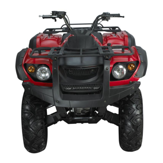
PowerMax 500 Bearclaw Maintenance Manual (111 pages)
Powermax 500 Bearclaw ATV Maintenance Manual
Brand:
PowerMax
| Category:
Offroad Vehicle
| Size: 7 MB
Table of Contents
Table of Contents
2
Catalogue
2
General Information
5
Engine no
7
Frame no
7
Identification Code
7
Height Gauge
8
Oil Filter Detacher
8
Outside Micrometer
8
Special Tools, Instruments and Meters
8
Dial Indicator
9
Diameter of a Hole
9
Multimeter
9
Torque Spanner
9
Periodic Maintenance Chart
10
Snap Ring Clamp
10
To Detach the Magneto
10
Description
5
2 Inspection and Adjustment of Engine
11
Check the Pressure of Cylinder
11
Check the Valve Clearance
12
Valve Clearance
13
Spark Plug Checking
14
Unplug the Spark-Plug Cap
14
Cylinder, Piston, Piston Ring
15
Diagnosing and Eliminating of Malfunction
16
Overheated
16
Repairing Limit Value
17
Right-Angle Intersection
17
Inspection of Piston and Piston Ring
17
Extreme Position
19
Measure the External Diameter of Piston Pin
19
Inspection of Crank and Connecting Rod
20
Inspection of Clutch
21
Inspection of Carburetor
21
Inspect the Idle of Carburetor
21
Inspection of Air Cleaner
22
Inspection of Oil Clarifier
22
Inspection of Lubrication System
23
Inspection of Oil Pump
23
Flow of Oil Pump
23
Lubrication of Engine
24
Inspection of Cylinder Head
24
Remove and Examine the Width of Valve.
25
Measure the Width of Mating Surfaces of Valve
26
Inspection of Valve Spring
27
Examining Lifting Distance of Cam
27
Inspection of Rocker Arm
28
Inspection of Rocker Arm Shaft
28
3 Disassembly of Engine
29
Cylinder Head and Block
29
Piston and Connecting Rod
34
Remove Pull-Out Hand Start Assembly
35
Left Crankshaft Case Cover
36
Magneto
36
Remove the Stator Coil
36
Remove the Pulse Coil
36
Oil Pump
37
Clutch
38
Structure of Carburetor
40
Inspection and Adjusting
42
Decomposition
42
Remove the Evacuated Chamber Cover
42
Remove Permanent Seat
42
Remove Pilot Screw
43
Remove Pontoon Chamber Cover
43
Shim
44
Check the Carburetor Body
45
Check the Pontoon
45
Check the Pontoon Triangular Needle
46
Triangular Needle Seat
46
Check the Piston Valve
46
Check the Main Jet
47
4 Chassis
48
Steering Operation System
48
Structure of Steering Vertical Column
48
Components of Steering Bar
49
Disassembly, Inspection and Assembly of Steering Vertical Column
50
Hexagon Flange Bolt M8×30
50
Vertical Column
51
Inspection of Steering Vertical Column Components
52
Inspection Method
54
Rotating Torque of the Steering Vertical Column
54
Assembly of Steering Vertical Column
54
Disassembly of Steering Bar
57
Inspection of Steering Bar
57
Assembly of the Steering Bar
58
Brake System
59
Front Disk Brake Components
59
Disassembly of Front Disk Brake Plate
62
Disassembly of the Front Disk Brake System
63
Remove the Front Fuel Pipe Bracket
64
Inspection of the Front Brake System
64
Assembly of Front Brake System
66
Assemble Front Wheel Components Onto Front Wheel
66
Preparation for Inspection and Maintenance of the Rear Brake System
67
Disk Brake Plate
70
Disassembly of Rear Disk Brake System
70
Remove Rear Disk Brake System
71
Disassembly of Rear Disk Brake Plate
71
Remove Rear Wheel Components
71
Remove the Rear
72
Inspection of Rear Brake System
72
Assembly of Rear Brake System
73
Wheel and Tire
75
Preparation for Maintenance of Wheel
75
Disassembly of Wheel Components
76
Inspection of Wheel Components
76
Assembly of Wheel
76
Specification of Wheel and Tire
77
Transmission System
78
Fore Bridge
78
Front Tank Components
79
Disassembly of Fore Bridge Component
81
Sensor
81
Disassemble the Fore Bridge Differential
82
Inspection and Maintenance of Fore Bridge
82
Assembly of Fore Bridge Component
83
Rear Bridge
84
Transmission Case of Rear Bridge
84
Gear Shift Mechanism
85
Inspection and Maintenance of Gear Shift Mechanism
86
Suspension
87
Components of Rear Suspension
87
Rear Rocker Arm
88
Front Suspension
89
Inspection and Maintenance of Rear Suspension
92
5 Electrical System
92
Route Color Indication
92
Ignition System
96
The Key Diagram of Ignition Elements Ignition Elements
96
Charge System
97
The Key Diagram of Charge Elements
97
Magneto and Charge System
97
Battery
97
Lighting System
99
Meter and Signal System
100
Operation and Working Way
100
Headlight
100
Headlight Switch
100
Electrical Starting System
101
Starting Circuit
101
Starting System Working Process
101
Specification
102
Specification of Technique
102
Specification of Vehicle
102
6 Appendix
102
Specification and Model of Engine
104
Specification and Model of Other Parts and Structure
106
Performance Requirement
106
Starting Performance
106
Accelerating Performance
106
Climbing Power
107
Lowest Fuel Oil Consumption Rate
107
Reliability
107
Durability
107
Parking Performance
108
Front Illuminator Performance
108
The Side Leans the Steady Constant Angle
108
Requirements for Torque of Fastener
108
Electrical Circuits
109
Advertisement
Advertisement
Related Products
PowerMax 500 Rough-Rider
PowerMax 50-0550
PowerMax Categories
Treadmill
Battery Charger
Boiler
Fitness Equipment
Inverter
More PowerMax Manuals
Login
Sign In
OR
Sign in with Facebook
Sign in with Google
Upload manual
Upload from disk
Upload from URL