Sign In
Upload
Manuals
Brands
PowerLogic Manuals
Measuring Instruments
PM-620
PowerLogic PM-620 Manuals
Manuals and User Guides for PowerLogic PM-620. We have
1
PowerLogic PM-620 manual available for free PDF download: User Manual
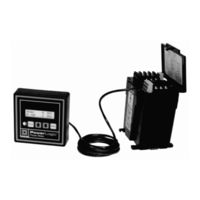
PowerLogic PM-620 User Manual (122 pages)
Power Meter Class 3020
Brand:
PowerLogic
| Category:
Measuring Instruments
| Size: 1 MB
Table of Contents
Technical Support
2
Table of Contents
5
Chapter 1-Introduction
9
What Is the Power Meter
9
Summary of Power Meter Instrumentation
10
Using this Bulletin
11
Not Covered in this Bulletin
11
Notational Conventions
11
Chapter 2-Safety Precautions
13
Chapter 3-Hardware Description
15
Display
15
3-1: Power Meter Display Components
16
3-2: Power Meter Display, Front and Back
17
Power Meter Connections
18
3-3: Front of Power Meter and Terminal Shield Label
18
Chapter 4-Installation
19
Power Meter/Display Mounting Options
19
Mounting the Display
20
In Existing 1% Ammeter/Voltmeter Cutout
20
On Panel Without Existing 1% Ammeter/Voltmeter Cutout
21
Mounting the Power Meter
22
Directly Behind the Display
22
Existing Ammeter/Voltmeter Cutout
23
Remote Mounting
24
4-2: Mounting Power Meter on Panel with no Existing Cutout
25
4-3: Panel Mount for the Power Meter Display
25
DIN Rail Mounting
26
4-4: Mounting Power Meter on 35 MM DIN Rail
27
Chapter 5-Wiring
29
Wiring Cts, Pts, and Control Power
29
Control Power Transformer (CPT) Sizing
30
Control Power Fuses
30
Metering Potential Transformers (Pts)
30
CE Compliance
30
5-1: Clamp-On Ferrite and Disconnect Breaker for CE Compliance
31
5-2: Opening the Clamp-On Ferrite
31
5-3: 3-Phase, 3-Wire Delta Direct Voltage Connection with 2 Cts
32
5-4: 3-Phase, 3-Wire Delta with 2 Pts and 2 Cts
33
5-5: 3-Phase, 3-Wire Delta with 2 Pts and 3 Cts
34
5-6: 3-Phase, 4-Wire Wye, Ground and Direct Voltage Connection, with 3 Cts
35
5-7: 3-Phase, 4-Wire Wye, Ground Connection, with 3 Pts and 3 Cts
36
5-8: DC Control Power Wiring
37
5-9: Power Meter Wire Routing
38
Deriving Control Power from Phase Voltage Inputs
39
Grounding the Power Meter
40
Solid-State KYZ Pulse Output
41
5-10: KYZ Pulse Output
41
5-11: Typical KYZ Pulse Output Connection for Use as an Alarm Contact
42
Chapter 6-Communications
43
Protocols
43
POWERLOGIC Protocol Communications Wiring
43
Connecting to a Personal Computer Via POWERLOGIC Communications
44
6-1: Power Meters Connected to a Personal Computer Via SY/LINK Card
44
Connecting to a POWERLOGIC Network Interface Module (PNIM) Using POWERLOGIC Communications
45
6-2: Power Meters Connected to a PNIM
45
Connecting to a SY/MAX Programmable Controller Using POWERLOGIC Communications
46
6-3: Power Meters Connected to a SY/MAX Programmable Controller
46
Modbus RTU Protocol
47
Jbus Protocol
47
Connecting to a PC Using Modbus or Jbus Communications
48
Length of the Communications Link (POWERLOGIC, Modbus, or Jbus)
49
Daisychaining PM&CS Devices (POWERLOGIC, Modbus, or Jbus)
49
Biasing the Communications Link (POWERLOGIC, Modbus, or Jbus)
50
Labeling the CAB-107 Leads
51
Terminating the Communications Link (POWERLOGIC, Modbus, or Jbus)
52
Terminating Power Meter with Terminal Block and MCT-485
53
Chapter 7-Display Operation
55
Introduction
55
Modes
55
Accessing a Mode
56
Setup Mode
57
Resets Mode
58
Diagnostics Mode
58
Display Modes
58
How the Buttons Work
59
Arrow Buttons
59
Contrast Button
59
Mode Button
59
Select Button
59
Setting up the Power Meter
60
Power Meter Setup Flowchart
61
Performing Resets
62
Viewing Diagnostic Information
63
Using Display Modes
63
Setting up Onboard Alarms (PM-650 Only)
63
Viewing Active Alarms (PM-650 Only)
64
Chapter 8-Metering Capabilities
65
Real-Time Readings
65
Min/Max Values (PM-650 Only)
65
Power Factor Min/Max Conventions
66
Power Factor Min/Max Example
67
Alternate VAR Sign Convention
68
Energy Readings
69
Power Analysis Values
70
Demand Readings (PM-620 and PM-650 Only)
71
Demand Power Calculation Methods
71
Sliding Block Interval Demand
71
Block Interval Demand with Subinterval Option
72
Peak Demand
72
Predicted Demand
72
Synch to Comms
72
KYZ Pulse Output
73
Calculating the Pulse Constant
73
Chapter 9-Onboard Alarming (PM-650 Only)
74
Setpoint-Driven Alarms
74
Setpoint-Controlled Relay Functions
75
Undervoltage
76
Unbalance Current
76
Unbalance Voltage
76
Chapter 10-Logging (PM-650 Only)
77
Alarm Log
77
Event Log
77
Data Log
77
Alarm-Driven Data Log Entries
77
Storage Considerations
77
Appendix A-Specifications
78
Appendix B-Dimensions
80
Appendix C-Communication Cable Pinouts
81
Appendix D-Additional Wiring Diagrams
82
D-1: Power Meter System Wiring Connections
83
D-1: 240/120 V 1-Phase, 3-Wire Direct Voltage Connection with 2 Cts
84
D-2: 3-Phase, 4-Wire Delta with 3 Pts and 3 Cts
85
D-3: 3-Phase, 4-Wire Wye, 3-Wire Load with 3 Pts and 2 Cts
86
Appendix E-Using the Command Interface
87
Appendix F-Register List
89
Appendix G-Modbus and Jbus Functions Supported
109
Appendix H-2-Wire Modbus or Jbus
111
Appendix I-Alarm Setup (PM-650 Only)
112
Appendix J-Calculating Log File Size (PM-650 Only)
116
Advertisement
Advertisement
Related Products
PowerLogic PM820
PowerLogic PM850
PowerLogic PM870
PowerLogic PM-600
PowerLogic PM-650
PowerLogic P-CUBE
PowerLogic Categories
Gateway
Measuring Instruments
Power Supply
Media Converter
Power Pack
More PowerLogic Manuals
Login
Sign In
OR
Sign in with Facebook
Sign in with Google
Upload manual
Upload from disk
Upload from URL