Sign In
Upload
Manuals
Brands
Power One Manuals
Inverter
TRIO-20.0-TL
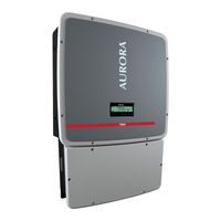
Power One TRIO-20.0-TL Solar Inverter Manuals
Manuals and User Guides for Power One TRIO-20.0-TL Solar Inverter. We have
1
Power One TRIO-20.0-TL Solar Inverter manual available for free PDF download: Instruction Manual
Power One TRIO-20.0-TL Instruction Manual (111 pages)
Brand:
Power One
| Category:
Inverter
| Size: 16 MB
Table of Contents
Introduction and General Information
2
Conditions of Warranty and Supply
2
Exclusions from the Supply
2
Table of Contents
3
Contents
3
Reference Number Index
6
Graphical Representation of References
6
The Document and Who It Is for
7
Purpose and Structure of the Document
7
List of Annexes
7
Staff Characteristics
7
Symbols and Signs
8
Field of Use, General Conditions
9
Intended or Allowed Use
9
Limits of the Field of Use
9
Improper or Disallowed Use
9
Characteristics
10
General Conditions
10
Models and Range of Equipment
11
Identification of the Equipment and the Manufacturer
11
Wiring Box Components
13
Standard / -S2 Version
13
S2X / -S2F Version
14
Principal Wiring Box Components
15
Characteristics and Technical Data
16
Tightening Torques
18
Overall Dimensions
18
Bracket Dimensions
19
Efficiency Curves
20
Power Derating
21
Power Reduction Due to Environmental Conditions
21
Power Reduction Due to the Input Voltage
21
Characteristics of a Photovoltaic Generator
23
Strings and Arrays
23
Description of the Equipment
24
Operating Diagram
24
Connection of Several Inverters Together
25
Notes on the Sizing of the System
25
Functionality and Components of the Equipment
26
Topographic Diagram of the Equipment
28
Protective Devices
30
Anti-Islanding
30
Ground Fault in the Photovoltaic Panels
30
String Fuses
30
Overvoltage Surge Arresters
30
Further Protective Devices
30
Safety and Accident Prevention
31
Safety Instructions and General Information
31
Hazardous Areas and Operations
32
Environmental Conditions and Risks
32
Signs and Labels
32
Thermal Hazard
33
Clothing and Protective Devices for Staff
33
Residual Risks
34
Table of Residual Risks
34
Lifting and Transport
35
General Conditions
35
Transport and Handling
35
Lifting
35
Unpacking and Checking
35
List of Supplied Components
36
Kit of Recommended Spare Parts
37
Weight of the Equipment Units
38
Installation
39
General Conditions
39
Environmental Checks
40
Installations above 2000 Metres
40
Installation Position
41
Wall Mounting
42
Operations Preparatory to PV Generator Connection
43
Checking the Correct Polarity of the Strings
43
Checking of Leakage to Ground of the Photovoltaic Generator
43
Choice of Differential Protection Downstream of the Inverter
43
Configuration of Single or Parallel-Connected Input Channels
45
Configuration of Parallel-Connected Channels
45
Configuration of Independent Channels (Default Configuration)
45
Channel Configuration Examples
46
Input Connection to the PV Generator (DC Side)
47
Connection of Inputs on the Standard and S2 Models
47
Connection of Inputs on the S2F / S2X Model
48
Procedure for Installing Quick Fit Connectors
49
String Protection Fuses (-S2F / S2X Models Only)
50
Sizing of Fuses
50
Grid Output Connection (AC Side)
52
Characteristics and Sizing of the Line Cable
52
Load Protection Switch (AC Disconnect Switch)
53
Connection to the AC Side Terminal Board
53
Communication Card
54
Connections to the Communication Card
55
Serial Communication Connection (RS485)
55
Procedure for Connection to a Monitoring System
56
Monitoring System Via Serial (RS485)
57
Monitoring System Via Radiomodule
58
Configurable Relay Connection
58
Connecting Environmental Sensors
60
Specifications of Environmental Sensors
60
Connection Diagrams for Environmental Sensors
61
Remote Control Connection
62
Auxiliary Output Connection
62
SD Card
62
Grid Standard Setting of the Country and Language Display
63
Grid Standard of the Country and Display Language Saving
64
Installing the Wiring Box Cover
65
Instruments
66
General Conditions
66
Display and Keypad
67
Description of Symbols and Display Fields
67
Description of the Keypad
68
Operation
69
General Conditions
69
Monitoring and Data Transmission
70
User Interface Mode
70
Types of Data Available
70
Commissioning
71
Display Access and Settings
73
Dynamic Behaviour of the Display
74
LED Behaviour
75
Specifications on the Behaviour of the Leds
76
Insulation Fault LED
76
Description of the Menus
77
Using the Panel Buttons
77
Statistics Menu
78
Settings Menu
80
Info Menu
87
AUTOTEST Procedure Conforming to Standard CEI 0-21
89
Performing the Tests that May be Conducted Using the Menu Appearing on the Display
89
Turning off the Inverter
92
Standard Wiring Box Version
92
Wiring Box Versions S2, S2F and S2X
93
Maintenance
94
General Conditions
94
Routine Maintenance
95
Troubleshooting
95
Alarm Messages
95
Dismantling the Inverter
102
Dismantling the Wiring Box
103
Resetting the Time Remaining to Change the Grid Standard
104
Associating a "New Component" after Replacement
105
Replacing the String Fuses (Versions S2F / S2X)
106
Replacing the Back-Up Battery
107
Verification of Ground Leakage
108
Behaviour of a System Without Leakage
108
Behaviour of a System with Leakage
109
Measuring the Insulation Resistance of Photovoltaic Generator
110
Storage and Dismantling
111
Storage of the Equipment or Prolonged Stop
111
Dismantling, Decommissioning and Disposal
111
Advertisement
Advertisement
Related Products
Power One TRIO-27.6-TL
Power One 10kW-SGTU-103
Power One 12.5kW-SGTU-1253
Power One 15kW-SGTU-153
Power One 17kW-SGTU-173
Power One 20kW-SGTU-203
Power One AURORA
Power One Aurora CCD
Power One Aurora CDD MICRO-0.25-I-OUTD-US-208
Power One Aurora CDD MICRO-0.25-I-OUTD-US-240
Power One Categories
Inverter
Battery Charger
Power Supply
Remote Control
Media Converter
More Power One Manuals
Login
Sign In
OR
Sign in with Facebook
Sign in with Google
Upload manual
Upload from disk
Upload from URL