Sign In
Upload
Manuals
Brands
POSEIDON Manuals
Air Compressor
PE 680-VE
POSEIDON PE 680-VE Air Compressor Manuals
Manuals and User Guides for POSEIDON PE 680-VE Air Compressor. We have
1
POSEIDON PE 680-VE Air Compressor manual available for free PDF download: Instruction Manual
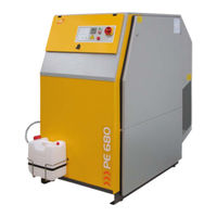
POSEIDON PE 680-VE Instruction Manual (96 pages)
High Pressure Breathing Air Compressors
Brand:
POSEIDON
| Category:
Air Compressor
| Size: 1 MB
Table of Contents
Table of Contents
7
Description
15
General
15
Purpose and Short Description
15
Design and Mode of Operation
15
Fig. 1 Compressor Unit, PE-VE Series; with Open
16
Fig. 2 Compressor Unit, PE-VE Series with
17
Fig. 3 Compressor Block IK12.14
18
Fig. 4 Compressor Block IK150, Front View
20
Fig. 5 Compressor Block IK180, Front View
21
Fig. 6 Compressor Block IK18.1, Front View
22
Technical Data
23
Lubrication System
27
Functional Description
27
Type of Oil
27
Fig. 7 Lube Oil Circuit, IK12.14
27
Fig. 8 Lube Oil System IK150 to IK18.1
27
Intake Filter
28
Functional Description
28
Intermediate Separators
28
1St Stage Separator (Option
28
Fig. 9 Intake Filter, IK12.14
28
Fig. 10 Intake Filter, IK150, IK180, IK18.1
28
Final Separator / Filter System
29
Function
29
• Pressure Maintaining/Non-Return Valve
29
Fig. 11 Filtersystem
29
Compressor Units up to 350 Bar
31
Compressor Units up to 420 Bar
31
Safety Valves
31
Pressure Gauges
31
Intermediate Pressure Gauges
31
Final Pressure Gauge
31
Oil Pressure Gauge
31
Fig. 12 Pressure Maintaining/Non-Return Valve, 350 Bar
31
Fig. 13 Final Pressure Gauge
31
Valves
32
Automatic Condensate Drain
32
Compressor Blocks Ik12.14, Ik150, Ik180
32
Fig. 14 Valve Operation
32
Fig. 15 Valve Head 1St Stage
32
Fig. 16 Automatic Condensate Drain Unit
32
Compressor Block Ik18.1
33
Fig. 17 Normal Operation
33
Fig. 18 Condensate Drain
33
Fig. 19 Automatic Condensate Drain Unit
34
Fig. 20 Drain Valve 2Nd Stage Separator
34
Start Unloading
35
Standstill Drainage
35
CONDENSATE COLLECTOR 10 Ltrs
35
Fig. 21 Normal Operation
35
Fig. 22 Condensate Drain
35
Fig. 23 Condensate Collector, 40 Ltrs
36
Fig. 24 Float Switch Orientation
36
Fig. 25 Condensate Collector, Function
36
Condensate Disposal
37
Electrical System
37
General
37
Emergency Shutdown
37
Compressor Control Unit B-Control Hw
37
Compressor Drive System
38
Cooling System
38
Fig. 26 Service Switch
38
Fig. 27 Cycle Counter
38
Fig. 28 Cooling Air Flow
38
Installation, Operation
41
Installation
41
Compressor Room Conditions
41
Locating the Unit
41
Natural Ventilation
41
Fig. 29 Room Temperature
41
Fig. 30 Locating the Unit
41
Fig. 31 Installation (Natural Ventilation
41
Fig. 32 Installation with Natural Ventilation, Example
42
Fig. 33 Installation with Natural Ventilation, Example
42
Artificial Ventilation
43
Fig. 34 Installation with Natural Ventilation
43
Fig. 35 Installation (Artificial Ventilation
43
Fig. 36 Installation with Artificial Ventilation
44
Fig. 37 Installation with Artificial Ventilation
44
Electrical Installation
45
Connecting External Filling
46
Panels (Optional
46
Connecting Storage Bottles
46
(Optional
46
Fig. 38 B-Controlr-HW Control Unit
46
Taking into Operation
47
Preparation for Operation
47
Fig. 39 Solenoid Valve
47
Operation
51
Safety Measures
51
Notes and Warning Signs
51
Identifying the Safety Notices
51
Fundamental Safety Notices
51
SAFETY REGULATIONS (EC; Partly Germany, Only)
54
Operation
54
Preparation for Operation
56
Starting the Unit
56
Filling Procedure
56
Fig. 40 Scavenging Valve
57
Fig. 41 Connecting Air Bottle
57
Fig. 42 International Filling Connector
57
Fig. 43 Filling Air Bottle
58
Fig. 44 Removing Air Bottle
58
Maintenance, Repair
63
General
63
Maintenance Record
63
Maintenance Work
63
Maintenance Intervals
63
Lubrication System
63
Oil Level Check
63
Fig. 45 Oil Sight Gauge IK12.14
63
Oil Change Intervals
64
Oil Capacity
64
Oil Packages
64
Oil Change
64
Changing the Oil Type
64
Fig. 46 Oil Sight Gauge IK150, IK180, IK18.1
64
Fig. 47 Oil Filler, IK12.14
64
Venting Oil Pump
65
Fig. 48 Oil Filler, IK150, IK180, IK18.1
65
Fig. 49 Removing the Cover
65
Fig. 50 Replacing the Oil Filter
65
Intake Filter
66
Maintenance
66
Fig. 51 Intake Filter, IK12.14
66
Fig. 52 Intake Filter, IK150, IK180, IK18.1
66
Fig. 53 Oil and Water Separator, 420 Bar
67
Fig. 56 Pressure Maintaining/Non-Return Valve 350 Bar
73
Fig. 57 Pressure Maintaining/Non-Return Valve 420 Bar
73
Fig. 58 Final Pressure Safety Valve, 225 and 330 Bar
73
Fig. 59 Safety Valve, 420 Bar
73
Fig. 60 Final Pressure Switch
75
Fig. 61 Filling Valve on External Filling Panel
76
Fig. 62 Torque Sequence
79
Advertisement
Advertisement
Related Products
POSEIDON PE 100-T
POSEIDON PE 250-MVE
POSEIDON PE 300-MVE
POSEIDON PE300-VE
POSEIDON PE320-VE
POSEIDON PE400-VE
POSEIDON PE 250-HE
POSEIDON PE 300-HE
POSEIDON PE 500-VE
POSEIDON PEEDB9393
POSEIDON Categories
Diving Instrument
Controller
Air Compressor
Safety Equipment
Measuring Instruments
More POSEIDON Manuals
Login
Sign In
OR
Sign in with Facebook
Sign in with Google
Upload manual
Upload from disk
Upload from URL