Sign In
Upload
Manuals
Brands
Polhemus Manuals
GPS
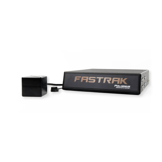
3SPACE FASTRAK
Polhemus 3SPACE FASTRAK Tracking System Manuals
Manuals and User Guides for Polhemus 3SPACE FASTRAK Tracking System. We have
1
Polhemus 3SPACE FASTRAK Tracking System manual available for free PDF download: User Manual
Polhemus 3SPACE FASTRAK User Manual (124 pages)
Brand:
Polhemus
| Category:
GPS
| Size: 1 MB
Table of Contents
Table of Contents
3
List of Figures
5
1 Getting Started
6
Figure 1-1 Complete FASTRAK System
6
Figure 1-2 Transmitter Connection
7
Figure 1-3 Receiver Connection
7
Figure 1-4 Mounting Transmitter and Receiver on 2X4
7
Figure 1-5 Power Connector
8
Figure 1-6 DC Power Cable Installation
8
Figure 1-7 DC USB Cable Installation
9
Figure 1-8 Pimgr Screen Display
10
Figure 1-9 RS-232 Configuration Settings
11
Figure 1-10 FASTRAK Data Record Display
11
2 Contacting Polhemus Customer Service
13
3 Current Fastrak Vs. Previous Versions
14
4 Fastrak Commands Index
15
5 Technical Overview
16
6 Specification
17
Position Coverage
17
Angular Coverage
17
Static Accuracy
17
Resolution Vs. Range
17
Latency
17
Output
17
Update Rate
17
Carrier Frequency
18
Interface
18
USB Interface
18
Operating Environment
18
Operating Temperature
18
Physical Characteristics
18
Power Requirements
19
7 Component Description
20
Seu
20
Transmitter Port
20
Figure 7-1 FASTRAK SEU, Front View
20
Figure 7-2 FASTRAK SEU, Rear View
20
Receiver Ports (4)
21
Power Indicator
21
I/O Select Switch
21
External Sync I/O
22
Figure 7-3 Default I/O Select Dip Switch Settings
22
Frequency Select Module
23
I/O
23
Figure 7-4 Sync Connector Identification (Input and Output)
23
Usb I/O
24
Optional Rs-422 I/O
24
Figure 7-5 RS-232 Cable Connection
24
Video Sync Input
25
Power Input Receptacle
25
Transmitter
25
Figure 7-6 Transmitter Diagram
26
Figure 7-7 Transmitter
26
Receiver(S)
27
Figure 7-8 RX2 Receiver Dimensions (in Inches)
27
Figure 7-9 RX1-D Receiver (in Inches)
28
Figure 7-10 Receiver
28
Stylus
29
Video Sync Detector
30
Figure 7-11 Stylus Dimensions
30
Figure 7-12 Stylus
30
Long Ranger Transmitter
31
4" Transmitter
31
Short Ranger Transmitter
31
Mini Receiver
31
Figure 7-14 Video Sync Detector
31
8 System Operation
32
I/O Considerations
32
Powering U Pfastrak
32
Configuration Changes
33
Using the Usb Interface
33
Installing Usb Device Drivers
34
Figure 8-1 Connection of USB Cable to Switch to USB Mode
34
Synchronization
36
Internal Sync
36
External Sync
36
Video Sync
37
Multiple Systems Operation - Fastraks Produced as of January 2012
37
Output Considerations
37
9 System Commands
39
Command Format Notation and Convention
39
Command Format Notes
40
Command/Output Listing
41
Figure 9-1 System Alignment
41
A' - Alignment Reference Frame
42
B' - *Boresight
44
B' - *Unboresight
45
C' - Continuous Output Mode
46
C' - Disable Continuous Printing
47
D' - Enable Fixed Metal Compensation
48
D' - Disable Fixed Metal Compensation
49
E' - Define Stylus Button Function
50
F' - Enable ASCII Output Format
51
F' - Enable Binary Output Format
52
G' - Boresight Reference Angles
54
H' - Hemisphere of Operation
55
Figure 9-2 Hemisphere Vector
57
I' - Define Increment
58
L' - Active Station State
59
N' - *Define Tip Offsets
61
O' - Output Data List
62
System Data Record: ASCII Format
64
System Data Record: IEEE Floating-Point Format
66
O' - Set Output Port
67
P' - Single Data Record Output
68
Q' - Angular Operational Envelope
69
R' - *Reset Alignment Reference Frame
71
R' - Transmitter Mounting Frame
72
S' - System Status Record
73
T' - Built-In-Test Information
75
U' - English Conversion Units
77
U' - Metric Conversion Units
78
V' - Position Operational Envelope
79
V' - Attitude Filter Parameters
81
W' - Reset System to Defaults
84
X' - Configuration Control Data
85
X' - Position Filter Parameters
86
Y' - Set Synchronization Mode
88
K' - *Save Operational Configuration
90
Q' - *Resume Data Transmission
91
S' - *Suspend Data Transmission
92
Y' - *Reinitialize System
93
10 Command Error
94
11 Default Operation with a Stylus
95
APPENDIX A. Limited Warranty and Limitation of Liability
96
APPENDIX B. Trouble Shooting
98
APPENDIX C. Glossary
99
APPENDIX D. 'Accuracy and Resolution' White Paper
107
APPENDIX E. 'Latency' White Paper
113
APPENDIX F. Cable Diagrams
117
Index
121
Advertisement
Advertisement
Related Products
Polhemus G4 Radio
Polhemus G4-RF
Polhemus MINUTEMAN
Polhemus PATRIOT
Polhemus VIPER 16
Polhemus VIPER 4
Polhemus VIPER 8
Polhemus Categories
GPS
Measuring Instruments
More Polhemus Manuals
Login
Sign In
OR
Sign in with Facebook
Sign in with Google
Upload manual
Upload from disk
Upload from URL