Sign In
Upload
Manuals
Brands
Polar Instruments Manuals
Industrial Equipment
GRS550
Polar Instruments GRS550 Manuals
Manuals and User Guides for Polar Instruments GRS550. We have
1
Polar Instruments GRS550 manual available for free PDF download: User Manual
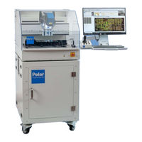
Polar Instruments GRS550 User Manual (151 pages)
Brand:
Polar Instruments
| Category:
Industrial Equipment
| Size: 8 MB
Table of Contents
European Community Directive Conformance Statement
9
Safety
10
Warning
10
Grounding
10
Power Cord Colour Codes
11
Line Voltage Setting
11
Grs550 Operation
12
Caution
12
Electrical Isolation
12
Specifications
13
Electrical
13
Nodal Impedance Test Facilities
13
Mechanical
13
Environmental Operating Conditions
14
Power Requirements
14
Line Fuses
14
Symbols
14
Accessories
15
Standard Accessories
15
Table of Contents
18
Introduction to the Grs550
25
The GRS550 Fixtureless Tester
25
Nodal Impedance Fault Finding
25
Rapid Program Creation
25
Fault Finding
26
External Instrument Control
26
Schematic Display
26
Nodal Impedance
26
CAD Netlist Files
27
Rapid Test File Generation
27
GRS550 Features
27
GRS550 Integrated Programming and Test Environment
27
Areas of Application
28
PC Control
28
Grs550 General Description
29
GRS550 Controls and Connectors
29
Front Panel
29
Main Table
29
Probe Head
29
Camera Head + Laser Pointer
29
Optional Bar Code/Matrix Code Reader
29
Rear Panel
30
Line Voltage Selection
30
USB3 Camera Connections
31
JOYSTICK Connector
31
LINK to PC Socket
31
EXT. CONNECTIONS to TABLE Socket
31
Channel a Probe Output
32
Channel a COM (Common Return) Connector
32
PROBE Output
32
PROBE COM (Common Return) Connector
32
Using the Manual GRS550 Probes
32
Connecting the Test Wires (PFL a and COM Sockets)
32
Switchable COM Sockets
32
Installing the Grs550
33
Unpacking
33
The GRS550 Operating Software
33
Software Remote Support
33
The GRS550 Environment
34
Getting Started with the Grs550
35
Starting the GRS550
35
Configuring the GRS550
35
Cam/Video
35
Prober/Bxd
36
Setting Screen Colours
37
Testing
38
Specifying Fault Entry
39
Setting System Prompts
40
Print Report
41
Adjustment
41
The GRS550 Screen
42
Using the GRS550 Windows
43
The GRS550 Menu System
44
Selecting Commands
44
The File Menu
45
Read CAD Netlist Command
46
Prober Menu
47
The Display/Info Menu
48
The Enhance Data Menu
49
Remove Data
49
Rename Vias
49
The Manual Programming Menu
50
The Keep out Areas Menu
50
The Test Points Menu
51
The Test List Menu
51
The Window Menu
52
The Configure Menu
53
The Help Menu
53
Using the GRS550 COM Sockets
54
Connecting the Test Cables
54
Live Instrument Testing
55
Live Instrument Screen
55
Defining Test Conditions
57
Test Range Selection
57
Selecting the Voltage Range
57
Selecting the Frequency Range
58
Resistive Signatures
58
Reactive Signatures
58
Semiconductor Signatures
60
Diode Signatures
60
Bus Signatures
61
Locating Faults on Bus-Connected Nets
61
Signature Stability
63
Cycle
65
Creating the Test List
66
Mounting the Board
66
Homing the GRS550
67
Calibrating the Probe
67
Creating the Test List (Programming Test Points)
69
Creating the Test List
69
Creating Test Points from CAD Data
69
Loading the CAD Netlist File
69
Removing Superfluous Data
71
Loading Gerber Plot Data
71
Creating Components
72
Creating the Component
73
Creating Test Points Manually
75
Creating a New Board
75
Manual Programming Tool Bar
76
Creating Alignment Points
76
Choosing Alignment Points
77
Creating Components Manually
79
Creating Single Point Components
79
Creating Single In-Line Packages
80
Creating Small Outline IC (SOIC) Devices
81
Creating Dual In-Line Package Devices
82
Determining Device Pin Pitch and Count
83
Creating Quad Flat-Pack Devices
84
Copying Devices
85
Adding a Qr/Bar Code Position
86
Linking Schematics to the Board Type
88
Searching for Components
88
Setting Alignment Points
89
Choosing Alignment Points from CAD Data
89
Excluding Areas of the Board from Testing
90
Advanced Keep out Options
91
Excluding Single Test Points and Components
91
Excluding Test Points and Components by Window
93
Allocating Test Points
93
Test Points Tool Bar Functions
94
Test Parameters
95
Test Point Allocation
96
Eliminating Test Points
96
Test Point Surface Selection
96
Editing the Test Point List Manually
97
Adding a Test Point
98
Deleting a Test Point
98
Adding and Deleting Test Points by Window
98
Offsetting a Test Point
98
Jogging a Test Point (for Device Based Allocation)
99
Jogging Test Points by Window
99
Offsetting Test Points on Round Pads
100
Undoing Test Point Movement
100
Removing Component Test Points
101
Saving the Board Information to a Database
101
Setting the Safe Fly Height
101
Moving Round the GRS550 Display
103
Changing the View Magnification (Zooming)
103
Panning the Display
103
Rotating the Display
104
Mirroring the Display
104
Moving the Display
104
Viewing Individual Layers
105
Controlling the Display
105
Display Extents
105
Display Options
105
Net Information
105
Highlighting Nets
106
Displaying Highlighted Nets
107
Point and Click
108
Fault Entry: Net Name
108
Fault Entry: Net Number
108
Fault Entry: Component and Pin
108
Displaying Highlighted Nets
108
Querying Pads and Test Points
109
Query Pad
109
Query Test Point
110
Testing Boards
111
The Test List Toolbar
111
The Test List Pane
112
The Component Pane
113
Modifying Test Parameters for Individual Devices
114
Setting Test Tolerances
115
Locating Devices
115
Component Pins List
115
Component Test Parameters
116
Acquiring Reference Signatures
117
Acquiring Reference Signatures for a Device
117
Acquiring Reference Signatures for the Whole Board
117
Inspection Mode - Verifying Probing Accuracy
119
Testing Components
120
Testing a Single Selected Component in Slow Motion
120
Testing a Single Selected Component
120
Sorting Signatures
121
Displaying Live Signatures
122
Testing Multiple Components
122
Testing Multiple Components Using Auto Align
122
Displaying the Test Summary
123
Clearing Test Results from a Component
124
CNT Critical Net Test
125
Replacing Reference Signatures for a Component
127
Using Alternate Signatures
127
Using Board Snapshots
128
Using Board Notes
128
Video Sectioning
129
Comparing Boards
130
Selecting Frames for Reference
130
Simplified User Interface
131
Status Light
131
Exiting the Program
131
Maintenance
133
GRS550 Basic Maintenance and Troubleshooting
133
Periodic Maintenance
133
Replacing the Test Pin
133
Replacing the Test Pin Carrier
133
Replacement of the Probe Head Linear Bearing
134
Replacement of the Probe Head Assembly
134
GRS550 Diagnostics Menu
134
Remote Troubleshooting
136
Reference
137
GRS550 Display Window Colours
137
Loaded Data Colours
137
Highlighted Item Colours
137
Keystroke and Mouse Functions
137
Pan and Zoom (Display/Info)
137
Query Items (Display/Info)
138
Enhance Data
138
Test Points
138
Keep out Areas
138
Testing
139
Activex Remote Control Command Set
141
Externalinstrumentsenabled
143
Enabledisableexternalinstruments
143
Align
143
Proberautoalign
143
Open_Grsdatabase
143
Tl_Testall
143
Testall_Autoalign
144
Retestonfail
144
Tl_Stoptest
144
Readbarcode
144
Tunebarcode
145
Focustunebarcode
145
Save_Snapshot
145
Printreport
145
Printsignatures
145
Printsignaturespassedtopdf
146
Printsignaturesfailedtopdf
146
Printsignaturesalltopdf
146
Getxyz(Intx,Inty,Intz)
146
Home
146
Prober_Fasthome
147
Movetopad(Strcomponent, Strpin)
147
Movetotestpoint(Strcomponent, Strpin)
147
Movetoxy (Intx,Inty)
147
Movez(Intz)
148
Parkz
148
Probeoffset(Intprobeorcrosshair)
148
Probeupdown(Intprobeposition)
148
Setswitchablecommons(Intswitchablecommonsvalue)
148
Switchcamera(Intcameraposition)
149
Touchz
149
Takecamerasnapshot
149
Proberotate
150
Getactualangle
150
Rfparkz
150
Rfmovez
150
Setlaserpointer
150
Rftouchz
151
Switchledringsonoff
151
Prober_Parkposition
151
Importcriticalnets
151
Testcnt()
151
Advertisement
Advertisement
Related Products
Polar Instruments GRS500
Polar Instruments TONEOHM 850A
Polar Instruments Categories
Test Equipment
Measuring Instruments
Industrial Equipment
Laboratory Equipment
More Polar Instruments Manuals
Login
Sign In
OR
Sign in with Facebook
Sign in with Google
Upload manual
Upload from disk
Upload from URL