Sign In
Upload
Manuals
Brands
PNI Manuals
Control Unit
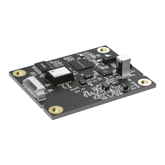
TRAX2 AHRS
User Manuals: PNI TRAX2 AHRS Heading Reference System
Manuals and User Guides for PNI TRAX2 AHRS Heading Reference System. We have
1
PNI TRAX2 AHRS Heading Reference System manual available for free PDF download: User Manual
PNI TRAX2 AHRS User Manual (84 pages)
Brand:
PNI
| Category:
Control Unit
| Size: 2 MB
Table of Contents
Table of Contents
2
Copyright & Warranty Information
5
Introduction
6
Specifications
7
Characteristics & Requirements
7
Table 3-1: Performance Specifications
7
Table 3-2: Absolute Maximum Ratings
8
Table 3-3: Electrical Requirements
8
Figure 3-1: Typical Current Drawing During Application of External Power
9
Table 3-4: I/O Characteristics
9
Table 3-5: Environmental Requirements
9
Table 3-6: Mechanical Characteristics
10
Mechanical Drawings
11
Figure 3-2: TRAX2 PCA Mechanical Drawing
11
Figure 3-3: Molex-To-Pigtail Cable Drawing, Pn 14476
11
Figure 3-4: Molex-To-USB Cable Drawing, Pn 14467
11
Set-Up
12
Electrical Connections
12
Table 4-1: TRAX2 Pin Descriptions
12
Installation Location
13
Operate Within the Trax2'S Dynamic Range
13
Locate Away from Changing Magnetic Fields
13
Mount in a Physically Stable Location
13
Mechanical Mounting
13
Pitch and Roll Convention
14
Coordinate System
14
Mounting Orientation
14
Figure 4-1: Positive & Negative Roll and Pitch Definition
14
Figure 4-2: TRAX2 Enclosed Mounting Orientations
15
User Calibration
16
Magnetic Calibration
16
Table 5-1: Magnetic Calibration Mode Summary
18
Full-Range Calibration
19
Table 5-2: 12 Point Full-Range Calibration Pattern
19
Figure 5-1: 12 Point Full-Range Calibration (Realistic View)
20
Limited-Tilt Calibration
21
Table 5-3: 12 Point 2D Calibration Pattern
21
Table 5-4: 12 Point Limited-Tilt Calibration Pattern
22
Table 5-5: 12 Point Limited-Tilt Calibration Alternative Pattern
22
Hard-Iron-Only Calibration
23
Accelerometer Calibration
23
Table 5-5: 6 Point Hard-Iron-Only Calibration Pattern
23
Operation with Trax Studio
25
Installation
25
TRAX Studio Header and Connecting to TRAX Studio
25
TRAX Studio Footer and Saving/Applying Settings
26
Configuration Tab
27
General Settings
28
Acquisition Settings
29
Calibration and the Calibration Tab
30
Calibration Settings
30
Performing a Calibration
32
Calibration Results
33
Test Tab
34
Log Data Tab
38
Graph Tab
39
System Log Tab
40
Operation with Pni Binary Protocol
41
Datagram Structure
41
Figure 7-1: Datagram Structure
41
Table 7-1: Port Configuration
41
Parameter Formats
42
Endianness
42
Floating Point
42
Signed Integer
43
Unsigned Integer
44
Boolean
44
Commands Overview
45
Table 7-2: TRAX2 Command Set
45
Set-Up Commands
46
Module Information
46
Module Configuration
47
Table 7-3: Configuration Identifiers
48
Table 7-4: Sample Points
49
Table 7-5: Merge Rate Identifiers
53
Saving Settings
54
Measurement Commands
54
Setting the Reference Magnetic Field Criteria
54
Data Acquisition Parameters
55
Data Components
56
Table 7-6: Component Identifiers
56
Making a Measurement
58
Continuous Data Output after Power Cycle
59
Calibration Commands
60
User Calibration Commands
60
Performing a User Calibration
62
Calibration Score
62
Factory Calibration
63
Compass Mode Commands
64
Switching Functional Mode
64
FIR Filters
65
Table 7-7: Recommended FIR Filter Tap Values
66
Power Down/Up
67
Using Multiple Coefficient Sets
68
Table 7-8: Multiple Coefficient Command List
69
Communication Protocol Example
71
Appendix - Sample Code
72
Advertisement
Advertisement
Related Products
PNI TCM5
PNI TCM3
PNI TRK504
PNI TCM2.6
PNI TCM2.5
PNI TV901
PNI TPW75
PNI Hunting TL700
PNI TargetPoint3
PNI Escort T1B
PNI Categories
Security Camera
Radio
Security System
Accessories
Security Sensors
More PNI Manuals
Login
Sign In
OR
Sign in with Facebook
Sign in with Google
Upload manual
Upload from disk
Upload from URL