Sign In
Upload
Manuals
Brands
PMA Manuals
Controller
KS800
PMA KS800 Manuals
Manuals and User Guides for PMA KS800. We have
3
PMA KS800 manuals available for free PDF download: Functional Description, Interface Manual, Operating Instructions Manual
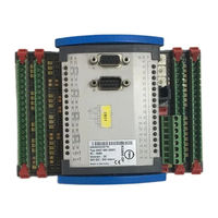
PMA KS800 Functional Description (84 pages)
Multi-Temperature Controller
Brand:
PMA
| Category:
Temperature Controller
| Size: 0 MB
Table of Contents
Table of Contents
3
1 Introduction
7
Basic Structure
7
Input
7
Functions
8
Output
8
2 Input Signal Processing
9
Measurement Value Pre-Processing
9
Measuring Frequency
9
Sensor Types
9
Thermocouples
9
Resistance Thermometer
10
Resistance
10
DC Voltage
10
Measurement Value Correction
11
Application Examples
12
Digital Input Signal Pre-Processing
12
Input Signal Distribution
12
Analog Input Signals
12
Digital Input Signals
13
3 Controller Block Diagram
14
Sequence Control
14
4 Set-Point Functions
15
Set-Point Control
15
5 Function Block Protocol
16
Data Structure
16
Structure of Configuration Words
17
Function Block Instrument
17
6 Controller Statuses and Status Priorities
21
Priority 0 Automatic
21
Priority 1 Tune, Run
21
Priority 2 Tune, Error
22
Priority 3 Sensor Break
22
Priority 5 Manual
22
Priority 7 Y_Track
23
Priority 8 Controller off
23
7 Automatic - Manual Switch-Over
24
8 Self-Tuning for Single-Loop Controllers
25
Preparation for Controller Self-Tuning
25
Process at Rest
25
Selecting the Stable Correcting Variable
25
Start from Automatic Mode
26
Start from Manual Mode
26
Self-Tuning Procedure with Heating
26
Self-Tuning Procedure with Heating and Cooling Processes: (3-Point Controller)
26
Set-Point Monitoring
27
Self-Tuning Several Controllers in a Group
27
Starting the Group Self-Tuning
27
Group Self-Tuning Stop
27
Common Start of the Heating Attempt for All Controllers of a Group
27
Common Start of the Cooling Attempt for All 3-Point Heating/Cooling Controllers
28
Signification of Self-Tuning Messages
28
9 Controlled Adaptation
29
Control Function Parameters
30
10 Signaller
31
11 Two-Point Controller
32
12 Three-Point DPID Controller
34
13 Three-Point Stepping Controller
36
14 Forcing of Switching Outputs
39
15 Continuous Controllers
40
16 Water Cooling
42
Water Cooling Controller Self-Tuning
44
17 Cascade Control
45
Configuration of a Simple Cascade
45
Controller Behaviour with Switch-Over
46
Master Controller Switch-Over from
46
Slave Controller Switch-Over
46
Interruption of Cascade Operation
46
Example of Cascade Control with up to 7 Slave Controllers
47
18 Start-Up Circuit
49
19 Mean Value Formation for the Output Hold Function
51
20 Heating Current Monitoring
52
Monitoring Cycle
52
Heating Current Alarm, Reset and Quick Test
53
21 Evaluation of Heating Current Measurement
54
Leakage Current Monitoring
54
Heating Current Scaling Factor
55
22 Alarm Handling
56
23 Configuration
58
General
58
Main Configuration Groups
58
C100 Main Controller Configuration
58
C101 Additional Controller Configuration
59
Control Loop Monitoring (Loop Alarm)
60
C150 Heating Current and Output Monitoring
61
C151 Additional Heating Current Configuration
62
C180 Analog Signal Allocation
62
C190 Digital Signal Allocation
63
Inputs
64
C200 Main Configuration
64
Input Scaling
65
C201 Input Scaling Start
65
C202 Input Scaling End
65
C205 Additional Configuration
66
C210 External Temperature Compensation
66
C213 Sensor Failure
67
C214 Filter Time Constant
67
Configuration Examples
68
Thermocouples
68
Resistance Thermometer
68
Voltage
68
C302 Heating Current Input
68
Outputs
69
C500 Signal Inputs/Outputs
69
Alarm Outputs
70
Action C530
70
Analog Outputs
71
C600, C602, C603, C604 Type of Alarms
72
C601 Alarm Target
73
C700 Controller Self-Tuning
74
Additional Functions
75
C900 Baud Rate COM1 PC Interface
75
C901 COM1 Address
75
COM2 Interface
76
C902 Baud Rate COM2 Bus Interface
77
C903 COM2 Address
77
C904 Mains Frequency, Alarm and Current Output Configuration
78
24 Special Functions
79
Selective Mean Value Formation
79
Configuration
81
Safety Limiter with Holding Function
82
Advertisement
PMA KS800 Interface Manual (54 pages)
Multi Temperaturecontroller PROFIBUS-DP
Brand:
PMA
| Category:
Controller
| Size: 2 MB
Table of Contents
Table of Contents
5
1 General
7
Scope of Delivery
8
2 Hints on Operation
9
Forcing
9
3 Process Data
10
Interface Connection
9
Installation of Cables
9
Defined as Status Byte Are
14
Disabling Mechanism with Changes
17
Process Data Transmission
17
Status and Diagnosis Messages
17
Parameter Transmission
18
Message Elements
18
General Communication Structure
19
Data Write Sequence
19
Data Read Procedure
20
Examples
20
Function Block Protocol Principles
20
Individual Access
20
Block Access (Tens Block)
21
Block Acces (Overall Block)
21
Data Types
23
4 Quick Entrance
24
Quick Entrance with S5
24
Example of a Test Environment
24
Quick Entrance with S7
26
Example of a Test Environment
26
5 Function Block Protocol
28
Data Structuring
28
CODE Tables
29
Structure of Configuration Words (C.XXXX)
29
INSTRUMENT (FB No.: 0 Type No.: 0)
29
Special Accesses
35
Type No.: 10)
35
Freely Configurable
36
Type No.: 20)
36
Input
38
Type No.: 112)
38
Contr
39
Type No.: 91)
39
Alarm
43
Type No.: 46)
43
6 Function Modules
45
Function Module for SIMATIC ® S5
45
Structure
45
Function Module Call
47
Function Module for SIMATIC ® S7
48
Structure
48
7 Annex
51
GSD File
51
Terms
51
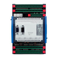
PMA KS800 Operating Instructions Manual (36 pages)
Multi-Temperature-Controller
Brand:
PMA
| Category:
Temperature Controller
| Size: 0 MB
Table of Contents
Table of Contents
3
1 Safety Hints
5
Electromagnetic Compatibility
5
2 General
6
Versions
6
Possible Output Configurations
7
3 Installation
7
Mounting
7
Dismounting
8
4 Electrical Connection
9
Terminals
9
Bus-Stecker
10
Galvanic Isolations
11
Supply Voltage
12
Fuses
12
5 Inputs
13
Analog Inputs
13
Thermocouple Inputs
13
Cold-Junction Temperature Compensation
14
DC Voltage
14
Resistance Thermometer
15
Screening
15
Heating Current Measurement and Heating Current Alarm
15
Input Circuit Examples
17
Digital Inputs
17
Input/Output Forcing
18
6 Outputs
19
Controller Outputs
19
Controller Outputs, Continuous
20
Analog Output Allocation
20
Alarm Outputs
21
Constant Voltage and Auxiliary Relays
22
7 Circuit Diagrams
23
Input/Output Circuit Diagram
23
KS 800 Overall Connecting Diagram With/Without Continious Outputs
24
KS 800 Overall Connecting Diagram with Constant Voltage 10V
25
8 Digital Interfaces
26
Engineering Tool Interface
26
BUS Interfaces
26
BUS-Connector
26
Devicenet Adaptor
27
COM2 Interface
28
Terminating Resistors
29
Advertisement
Advertisement
Related Products
PMA KS 50-1
PMA KS 52-1
PMA KS 45
PMA KS 50
PMA KS 40
PMA KS 90
PMA KS40-1
PMA KS 98
PMA KS98Plus
PMA KS10-I
PMA Categories
Controller
Temperature Controller
Measuring Instruments
Automobile Accessories
Transmitter
More PMA Manuals
Login
Sign In
OR
Sign in with Facebook
Sign in with Google
Upload manual
Upload from disk
Upload from URL