Sign In
Upload
Manuals
Brands
Phoenix Contact Manuals
Controller
MCR-FL-D-T-2SP-230
Phoenix Contact MCR-FL-D-T-2SP-230 Manuals
Manuals and User Guides for Phoenix Contact MCR-FL-D-T-2SP-230. We have
1
Phoenix Contact MCR-FL-D-T-2SP-230 manual available for free PDF download: Manual
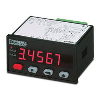
Phoenix Contact MCR-FL-D-T-2SP-230 Manual (63 pages)
Process Controller for thermocouples measuring resistors resistance thermometers sensors im mV range with 2 alarms
Brand:
Phoenix Contact
| Category:
Controller
| Size: 2 MB
Table of Contents
Deutsch
3
Table of Contents
3
1 Sicherheits- und Warnhinweise
4
Bestimmungsgemäßer Gebrauch
4
2 Technische Daten
4
Allgemeine Angaben
4
Elektrische Daten
4
Stromversorgung
4
Eingänge
4
Ausgänge
5
Mechanische Daten
5
Umgebungsbedingungen
5
Lieferumfang
6
Bestellschlüssel
6
3 Einbau
6
4 Elektrische Anschlüsse
6
Messeingänge
6
Spannungsversorgung und Grenzwert-Ausgänge
7
5 Parametrieren
7
Parametriermodus
7
Eingangsparameter für Momentanwert
8
Meßsignal Wählen
8
Thermoelemente
8
Thermoelementtyp Wählen
8
Anzeigeeinheit Wählen
8
Vergleichsstellenkompensation Wählen
8
Externe Vergleichsstellentemperatur Einstellen
8
Widerstandsmessung
9
Messbereich Wählen
9
Anzeigeeinheit Wählen (Pt100/Pt1000)
9
Korrekturwert Einstellen (Pt100/Pt1000)
9
Dezimalpunkt Wählen (400Ω/4000Ω)
10
Kennlinie Ändern (400Ω/4000Ω)
10
Meßsignal 0
10
Dezimalpunkt Wählen
10
Kennlinie Ändern
10
Meßsignal -100
10
Bereichsgrenzen Ändern
10
Anzeigekennlinie Parametrieren
11
Anzahl der Stützstellen Eingeben
12
Weitere Stützstellen Definieren
12
Grenzwert 1/Grenzwert-Ausgang 1
12
Grenzwert 1 Aus-/Einschalten
12
Hysterese für Grenzwert 1
13
Latch-Signal auf Grenzwert-Ausgang 1 Rücksetzen
14
Signalform für Grenzwert-Ausgang 1 Wählen
14
Grenzwert 2 / Grenzwert-Ausgang 2
14
Grenzwert 2 Aus-/Einschalten
14
Mode für Grenzwert-Ausgang 2 Wählen
14
Hysterese für Grenzwert 2
14
Latch-Signal auf Grenzwert-Ausgang 2 Rücksetzen
14
MIN/MAX-Erfassung
14
MIN-Wert Überwachen
15
MIN-Wert Rücksetzbar
15
Netzbrummfilter
15
Defaultwerteinstellung
15
Ende der Parametrierung
15
Parametrierung Überprüfen/Ändern
15
6 Betrieb
16
Anzeige IM Betrieb Umschalten
16
Grenzwerte IM Betrieb Einstellen
17
Rücksetzen der MIN/MAX-Werte
17
Display-Hold
17
English
18
1 Safety Instructions and Warnings
19
Use According to the Intended Purpose
19
2 Technical Data
19
Miscellaneous Data
19
Electrical Data
19
Power Supply
19
Inputs
19
Outputs
20
Mechanical Data
20
Environmental Conditions
20
Delivery
21
Order Code
21
3 Mounting
21
4 Electrica Connections
21
Control Inputs and Auxiliary Signals
22
Power Supply and Outputs
22
5 Parameter Setup
22
Select Range for the Input Signal
23
Thermocouples
23
Select Type of Thermocouples
23
Cold Junction Compensation
23
Correction Value
23
Resistance Measurement
24
Select Measuring Mode
24
Measurement Range
24
Display Unit (Pt100/Pt1000)
24
Correction Value (Pt100/Pt1000)
24
Decimal Point (400Ω/4000Ω)
25
Changing the Scaling Slope (400Ω/4000Ω)
25
Input Range 0
25
Decimal Point for Displayed Value
25
Changing the Scaling Scope
25
Input Range -100
25
Select Decimal Point
25
Changing the Range Limits
25
Setting the Scaling Slope
26
Enter the Number of Scaling Points
27
Alarms/Alarm Outputs
27
Alarm 1 Off/On
27
Reset Latch Signal at Output 1
28
Select Signal Form for Output Threshold 1
28
Reset Latch Signal at Output 2
29
MIN/MAX Value Acquisition
29
Reset Maximum Value
30
Monitor Minimum Value
30
Reset Minimum Value
30
Mains Hum Filter
30
Setting Default Values
30
End of Setup
30
Check/Alter Parameters
30
Operation
31
Resetting the MIN/MAX Value
32
Display Hold
32
Français
33
1 Instructions de Sécurité Et Avertissements
34
Utilisation Conforme
34
2 Caractéristiques Techniques Générales
34
Informations Générales
34
Caractéristiques Électriques
34
Tension D'alimentation
34
Entrées
34
Sorties
35
Caractéristiques Mécaniques
35
Conditions D'environnement
35
Pièces Livrées
36
Référence de Commande
36
3 Montage
36
4 Raccordements Électriques
36
Entrées de Mesure
36
Tension D'alimentation
36
5 Paramétrage
37
Mode de Paramétrage
37
Choix du Signal de Mesure
38
Thermocouples
38
Choix du Type de Thermocouple
38
Unité Affichée
39
Réglage de la Valeur de Correction
39
Mesure Par Résistance
39
Définition de la Méthode de Mesure
39
Définition de la Plage de Mesure
39
Unité Affichée (Pt100/Pt1000)
39
Réglage de la Valeur de Correction (Pt100/Pt1000)
39
Point Décimal (400Ω/4000Ω)
40
Modification de la Courbe de Fonctionnement (400Ω/4000Ω)
40
Signal de Mesure 0
40
Point Décimal
40
Modification de la Courbe de Fonctionnement
40
Signal de Mesure -100
40
Modification des Limites de la Plage
40
Modification de la Courbe de Fonctionnement
41
Paramétrage la Courbe de Fonctionnement de L'affichage
41
Détermination du Nombre de Points Caractéristiques
42
Définition du Premier Point Caractéristique
42
Définition du Deuxième Point Caractéristique
42
Définition des Points Caractéristiques Supplémentaires
42
Valeur Limite 1/Sortie de Valeur Limite1
42
Activation / Désactivation de la Valeur Limite 1
42
Sélection du Mode Pour la Sortie de Valeur Limite 1
42
Hystérésis Pour la Valeur Limite 1
43
Réinitialisation du Signal Latch Sur la Sortie de Valeur Limite
43
Choix de la Forme du Signal Pour la Sortie de Valeur Limite1
43
Activation / Désactivation de la Valeur Limite 2
44
Sélection du Mode Pour la Sortie de Valeur Limite 2
44
Hystérésis Pour la Valeur Limite 2
44
Réinitialisation du Signal Latch Sur la Sortie de Valeur Limite 2
44
Acquisition MIN/MAX
44
Surveillance de la Valeur Maximale
44
Réinitalisation de la Valeur Maximale
45
Surveillance de la Valeur Minimale
45
Réinitalisation de la Valeur Minimale
45
Filtre Antironflement
45
Rétablissement des Valeurs de Réglage Par Défaut
45
Vérification/Modification du Paramétrage
45
6 Fonctionnement
46
Modification de L'affichage Pendant Le Fonctionnement
46
Réglage des Valeurs Limite Pendant Le Fonctionnement
47
Réinitialisation des Valeurs MIN/MAX
47
Mise en Mémoire (Display-Hold)
47
Español
48
1 Instrucciones de Seguridad y de Advertencia
49
Empleo Normal
49
2 Información Técnica
49
Datos Generales
49
Información Eléctrica
49
Alimentación de Corriente
49
Entradas
49
Salidas
50
Información Mecánica
50
Condiciones Ambientales
50
Contenido a Entregar
51
Clave de Pedido
51
3 Montaje
51
4 Conexiones Eléctricas
51
Entradas de Medición
51
5 Parametraje
52
Modo de Parametraje
52
Parámetros de Entrada para Valor Momentáneo
53
Seleccionar la Señal de Medición
53
1Termopares
53
Seleccionar el Tipo de Termopar
53
Seleccionar la Unidad del Indicador
53
Seleccionar la Compensación de Los Extremos Libres
53
Ajustar la Temperatura de Los Extremos Libres
53
Ajustar el Valor de Corrección
54
Medición de Resistencia
54
Determinar el Método de Medición
54
Seleccionar la Escala de Medición
54
Seleccionar Unidad del Indicador (Pt100, Pt1000)
54
Valor de Corrección (Pt100, Pt1000)
54
Seleccionar la Coma Decimal (400 Ω/4000 Ω)
55
Modificar la Curva Característica (400 Ω/4000 Ω)
55
Señal de Medición 0
55
Seleccionar la Coma Decimal
55
Modificar la Curva Característica
55
Señal de Medición -100
55
Modificar Los Límites de Escala
55
Modificar la Curva Característica
56
Parametrar la Curva Característica de Indicación
56
Introducir el Número de Puntos Básicos
57
Definir el Primer Punto Básico
57
Definir el Segundo Punto Básico
57
Valor Límite 1/Salida de Valor Límite 1
57
Activar O Desactivar el Valor Límite 1
57
Seleccionar el Modo para la Salida de Valor Límite 1
57
Histéresis para el Valor Límite 1
58
Reiniciar la Señal Latch en la Salida de Valor Límite 1
58
Valor Límite 2/Salida de Valor Límite 2
59
Activar O Desactivar el Valor Límite 2
59
Seleccionar el Modo para la Salida de Valor Límite 2
59
Histéresis para el Valor Límite 2
59
Detección MÍN/MÁX
59
Valor Máximo Restablecible
60
Vigilar el Valor MÍN
60
Valor MÍN Restablecible
60
Filtro contra Zumbidos en la Red
60
Ajustar el Valor por Defecto
60
Finalización del Parametraje
60
Revisar/Modificar el Parametraje
60
6 Funcionamiento
61
Conmutar el Indicador en Funcionamiento
61
Ajustar Los Valores Límite en Funcionamiento
62
Reiniciar Los Valores MÍN/MÁX
62
Display-Hold
62
Advertisement
Advertisement
Related Products
Phoenix Contact MCR-FL-D-T-2SP-24
Phoenix Contact MCR-FL-D-U-I-2SP-24
Phoenix Contact MCR-FL-D-U-I-2SP-230
Phoenix Contact MCR-SL-D-U/I
Phoenix Contact MCR-SL-D-SPA-UI
Phoenix Contact MCR-F-UI-DC
Phoenix Contact MCR-SL-D-FIT
Phoenix Contact MINI MCR-SL-UI-UI
Phoenix Contact MACX MCR-CONF
Phoenix Contact mGuard series
Phoenix Contact Categories
Controller
Switch
Power Supply
Control Unit
Industrial Equipment
More Phoenix Contact Manuals
Login
Sign In
OR
Sign in with Facebook
Sign in with Google
Upload manual
Upload from disk
Upload from URL