Sign In
Upload
Manuals
Brands
Phoenix Contact Manuals
Controller
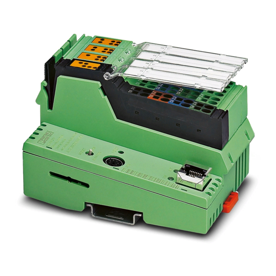
ILC 131 STARTER KIT
Phoenix Contact ILC 131 STARTER KIT Manuals
Manuals and User Guides for Phoenix Contact ILC 131 STARTER KIT. We have
1
Phoenix Contact ILC 131 STARTER KIT manual available for free PDF download: User Manual
Phoenix Contact ILC 131 STARTER KIT User Manual (92 pages)
User manual
Brand:
Phoenix Contact
| Category:
Controller
| Size: 2 MB
Table of Contents
Table of Contents
5
1 General
7
Introduction
7
Information about this Document
7
Content of the ILC 131 STARTERKIT
7
Components of the ILC 131 STARTERKIT
8
System Requirements
9
Supported Operating Systems
9
Hardware Requirements
9
Programming Software
9
Required Firmware Version
9
Required Programming Software
9
2 Installed Hardware and Startup
11
Installed Hardware
11
Structure of the Starter Kit
11
ILC 131 STARTERKIT: Installed Components on the Board
11
Wiring the Inputs
12
ILC 131 STARTERKIT: Example Wiring for the Inputs and the Supply Lines
12
Inputs Used in the Example
12
Establishing the Ethernet Connection
13
ILC 131 STARTERKIT: Example of the Ethernet Cabling
13
Starting up the ILC 131 STARTERKIT
14
Connecting the Supply Voltage
14
Example Projects
14
3 Installing the PC WORX EXPRESS Software
15
Installing the Software
15
Prior to Installation
15
Starting the PC WORX EXPRESS Installation Program
15
Starting PC WORX EXPRESS
16
4 Helpful Information about PC WORX EXPRESS
17
Online Help
17
The PC WORX EXPRESS User Interface
17
User Interface
17
Toolbars
18
Workspaces
19
IEC Programming Workspace
19
Bus Configuration Workspace
20
Process Data Workspace
20
Bus Structure" Window
22
Icons in the "Bus Structure" Window
22
Display in the "Bus Structure" Window
23
Examples of Different Device Representations
24
Compiling and Transmitting a Project and Performing a Cold Restart
25
Compiling a Project
25
Sending a Project
25
Project Control Dialog
25
Download Options" Dialog Box
26
Performing a Cold Restart
28
Compiling (Additional Information)
28
5 Step-By-Step Development of an Example Project
29
Creating a Project in PC WORX EXPRESS, Establishing a Connection to the Controller, and Reading in INTERBUS Devices
30
Overview
30
Creating a New Project
30
Project Creation Sequence
30
Adapting the Project Information
32
Project Information after Creating a New Project
32
Assigning the IP Address for the Controller
34
Select "PROFINET Configuration
35
Bus Configuration: Selecting the Controller
36
Figure 5-13 "Message Window" Following Bootp
40
Reading in INTERBUS
41
Figure 5-14 "View, Connected INTERBUS" Command
41
Figure 5-15: Selecting the ILC 131 ETH
42
Figure 5-16: Importing Devices into the Project
42
Figure 5-17 "Select Device" Window
43
Compiling and Sending a Project, and Performing a Cold Restart after Reading in the Bus Topology
44
Figure 5-18: Complete Bus Configuration for the Example Project
44
Figure 5-19: "Connected INTERBUS" Window: "Selected Control System - Offline
44
Firststeps_Ilc131" Example Project
45
General
45
Program Description
46
Figure 5-20 "Firststeps_Ilc131.Mwe" Complete Program
46
Creating the Program
48
IEC Programming Worksheet
48
Figure 5-21 IEC Programming Workspace
48
Entering a Comment
49
Figure 5-22: "Objects, Text (Comment)
49
Figure 5-23 "Comment" Dialog Box
49
Creating Variables
50
Figure 5-24: "Options" Dialog Box, "General" Tab: "Hide External Variables
50
Figure 5-25: "Variable Properties" Window - Icons
50
Step 1: Direct Linking of a Controller Input with a Controller Output Using Onboard Variables
51
Figure 5-26 Positioning the Cursor in the Worksheet of the POU "Main
51
Figure 5-27 Selecting the Onboard Variable: Input
51
Figure 5-28 Variable Properties (System Variables)
52
Figure 5-29 System Variable Created: Input
52
Figure 5-30 Selecting the Onboard Variable: Output
53
Figure 5-31 System Variable Created: Output
53
Figure 5-32 Connecting Variables
53
Figure 5-33: Compilation Process Completed Without Errors
54
Figure 5-34: Project Control Dialog
54
Figure 5-35 Download Process
54
Figure 5-36: Project Control Dialog
55
Step 2: Use of Function Blocks from the Function Block Library
56
Figure 5-37 Function Block in the Edit Wizard
56
Figure 5-38 Anding
56
Step 3: Connecting Function Blocks Using the Example of Clock Generation
58
Figure 5-39 Generating a Fixed Clock and Displaying It at a Controller Output
58
Figure 5-40 Creating a User Variable
59
Figure 5-41 Specifying the Time Constant
59
Figure 5-42: Generating a Variable Clock and Displaying It at a Controller Output
60
Figure 5-43: Creating a User Variable
61
Step 4: Direct Linking of Two Analog Value Variables/Process Data Assignment/Complete Program
62
Figure 5-44 Analog Value Variables
62
Figure 5-45 Variable Properties (Analog Value)
63
Figure 5-46: Process Data Assignment
64
Operation and Debug Mode - Viewing Values Online
65
Figure 5-47 Variables in Debug Mode: Program Variables
65
Figure 5-48: Variables in Debug Mode: Global Variables
66
Figure 5-49: Variables in Debug Mode: POU "Main" Variables (Examples)
67
6 Additional Functions of PC WORX EXPRESS
69
Diagnostics with Diag
69
7 Visualization with Webvisit
77
General
77
Loading the Visualization on the Controller
80
Starting the Visualization
84
A Appendixes
87
Appendixes
87
List of Figures
87
List of Tables
91
Advertisement
Advertisement
Related Products
Phoenix Contact ILC 130 ETH
Phoenix Contact ILC 150 ETH
Phoenix Contact ILC 155 ETH
Phoenix Contact ILC 191 ME/AN
Phoenix Contact ILC 191 ME/INC
Phoenix Contact ILC 2050 BI-L
Phoenix Contact ILC 350 Series
Phoenix Contact ILC 330
Phoenix Contact ILC 330 ETH
Phoenix Contact ILC 350 ETH
Phoenix Contact Categories
Controller
Switch
Control Unit
Power Supply
Media Converter
More Phoenix Contact Manuals
Login
Sign In
OR
Sign in with Facebook
Sign in with Google
Upload manual
Upload from disk
Upload from URL