Sign In
Upload
Manuals
Brands
PEWA Manuals
Test Equipment
ODEN AT
PEWA ODEN AT Manuals
Manuals and User Guides for PEWA ODEN AT. We have
1
PEWA ODEN AT manual available for free PDF download: User Manual
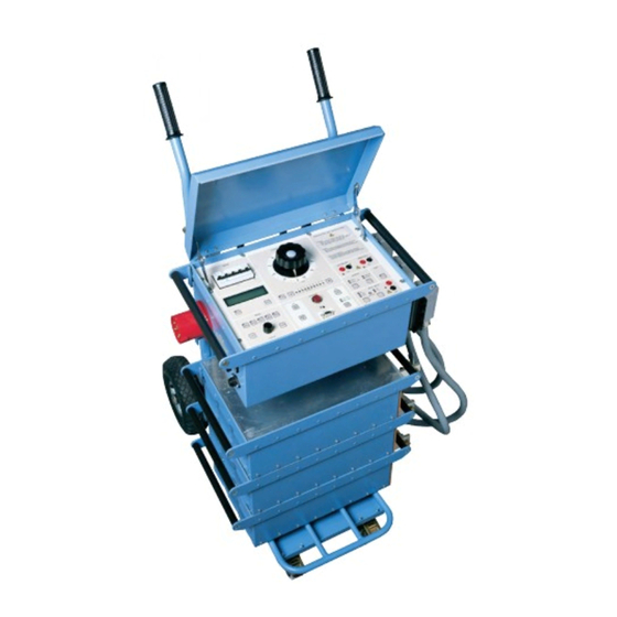
PEWA ODEN AT User Manual (114 pages)
High Current System
Brand:
PEWA
| Category:
Test Equipment
| Size: 7 MB
Table of Contents
Table of Contents
4
1 Safety Precautions
9
You Must Read the Following Safety Precautions Thoroughly
9
Precaution Levels
9
Precaution Level - DANGER
9
Precaution Level - WARNING
10
Precaution Level - Important
11
2 Introduction
13
General
13
Current Can be Generated in Many Ways
13
The Measurement Section Contains/Provides (Among Other Things)
13
Fields of Application
14
Reservations
15
3 Control Panel
17
Oden at Control Panel
17
MAINS Block
17
CURRENT ADJUST Block
18
VOLTMETER and A-METER 2 Block
18
OTPUT Block
18
AUX Block
18
STOP INPUT Block
18
MENU Block
20
DISPLAY Block
20
4 Display
21
The Display
21
Directional Indicators
21
When Special Applications Are Activated
21
5 Menu Options
23
General
23
AMMETER, V/A METER and SYSTEM Menu Options
23
A-Meter 1
24
System
25
MEMORY and APPLICATION Menu Options
25
Memory
25
Application
26
6 How to Install Oden at
27
Safety
27
Loading Oden at Onto a Carriage
27
Connecting the Test Object and the Current Units to each Other
28
Series Connection (Output HIGH I)
29
Parallel Connection (Output HIGH I)
30
Low-Current Output (Output 0-30V/60V)
30
Connecting Current Units to the Control Unit
31
Grounding Oden at
31
Connecting Oden at to the Mains
32
Mains Power Supply
32
Mains Voltage
32
Input Current
32
Mains Cable and Connectors
32
Current Cables and Conductors
33
Available Cable Sets
33
Standard Multi-Cable Sets
33
How to Arrange the Cable Sets
36
Minimising Impedance in Cables
36
How to Arrange Bars
38
To Get Equal Current from All Current Units
38
7 How to Use Oden at
39
How to Generate Current
39
Rules of Thumb When Generating Current
40
Setting the Desired Current
40
Low Currents
40
High Currents
40
Setting Times for Limited-Time Generation
41
Max Time
41
Continuous Current Generation
41
Getting Maximum Current from Oden at
42
Improving the Resolution of Current Settings
42
Generating Pulse Trains
43
Holding (Freezing) Measured Values
43
Measuring Phase Angle and Polarity
44
Measuring Z, P, R, X, S, Q and Power Factor (Cos )
45
Reading Maximun Current at an Operation
45
Measuring Operating Limits
46
Method 1: Normal Injection; Gradually Increase in Current
46
Method 2: Manually Controlled Momentary Injection
46
Method 3: Limited-Time Generation
47
Measuring Tripping/Operation Times
47
Instantaneous Trip Unit Measurement
48
Selecting Oden at Configuration and Current Cables
49
Introduction
49
Available Systems
49
Test Circuit Impedance Limits the Current
49
How to Succeed in Selecting a Suitable ODEN at System
50
Distance to the Test Object
50
Impedance of the Test Object
50
Procedure
50
Current Calculation Example
51
Examples
53
Example 1, Current Transformer
53
Example 2, Low Voltage Circuit Breaker
54
Example 3, Low Voltage Circuit Breaker
54
Form 1
55
Form 2
57
8 Application Examples
59
Testing a Low-Voltage Breaker
59
Testing the Ratio of a Current Transformer
60
Measuring the Polarity of a Current Transformer
61
Measuring the Resistances of Breakers and Electrical Connections (Microhmmeter Testing)
62
Testing a Direct Acting Automatic Recloser
63
Time Test
63
Testing a Sectionalizer
64
Testing a Ground Grid
65
9 Troubleshooting
67
General
67
Problem: no Current Is Sent out from Oden at
67
Problem: Not Possible to Switch on Oden at
67
Problem: Generation Stops Immediately or after Half a Cycle
67
Problem: Generation Does Not Stop When the Breaker Opens
67
Problem: Unexpected Value on Ammeter
67
The Display Is Dark
67
Error Messages
68
Current Units
68
Message: "Type X Curr Unit Not Installed
68
Message: "Curr Units Have Diff Settings
68
Message: "Curr Units Are of Diff Types
68
Measurement Errors
69
Problem: the Miniature Circuit Breaker F2 or the Mains Supply Fuse Trips
67
Problem: no Reading on Voltmeter and Ammeter 2
69
Problem: Time "0.000S" Is Displayed but Generation Continues
69
Problem
69
Problem: "AMP2=0A Amp1=0A"Is Displayed
69
Problem: "**** A"Is Displayed
69
Problem: Unexpectively Long Trip-Time While Testing Instantaneous Trip on a Circuit Breaker
69
10 Calibration
71
General
71
Calibration of Offset
71
Calibration of Scale Factor, Ammeter
72
Scale Factor, Range LOW
72
Scale Factor, Range HIGH
72
Scale Factor for the I/30-Function
72
Calibration of Scale Factor, Ammeter
73
Scale Factor, Range 0 - 2 a
73
Scale Factor, Range 0 - 20 a
73
Calibration of Scale Factor, Voltmeter
73
Scale Factor, Range 0 - 0.2 V
73
Scale Factor, Ranges 0 - 2 V, 0 - 20 V and 0 - 200 V
73
Resetting to Preset (Standardized) Calibration Values
74
Performing a Reset
74
11 Specifications
75
General
75
Output Specifications for 240 V Oden at Systems at 50 Hz
76
Oden AT/1S (240 V)
76
Oden AT/2S (240 V)
76
Oden AT/3S (240 V)
76
Oden AT/1X (240 V)
76
Oden AT/2X (240 V)
76
Oden AT/3X (240 V)
77
Oden AT/1H (240 V)
77
Oden AT/2H (240 V)
77
Oden AT/3H (240 V)
78
Load Curves, Oden at Systems
79
For 240 V
79
OUTPUT HIGH I, Oden at Systems for 240 V at 50/60 Hz Operation
79
OUTPUT HIGH I, Oden at Systems
80
For 240 V
80
OUTPUT 0-30V/60V, Oden at Systems for 240 V at 50/60 Hz Operation
82
OUTPUT 0-30V/60V, Oden at Systems for 240 V at 50 Hz Operation
83
Output Specifications for 400 V Oden at Systems at 50 Hz
84
Oden AT/1S (400 V)
84
Oden AT/2S (400 V)
84
Oden AT/3S (400 V)
84
Oden AT/1X (400 V)
84
Oden AT/2X (400 V)
85
Oden AT/3X (400 V)
85
Oden AT/1H (400 V)
85
Oden AT/2H (400 V)
86
Oden AT/3H (400V)
86
Load Curves, Oden at Systems
87
For 400 V
87
OUTPUT HIGH I, Oden at Systems for 400 V 50/60 Hz and 480 V 60 Hz
87
OUTPUT HIGH I, Oden at Systems
88
For 400 V
88
OUTPUT 0 - 30 V/60 V, Oden at Systems for 400 V 50 Hz
90
OUTPUT 0 - 30 V/60 V, Oden at Systems for 400 V 50 Hz
91
Output Specifications for 480 V Oden at Systems at 60 Hz
92
Oden AT/1S (480 V 60 Hz)
92
Oden AT/2S (480 V 60 Hz)
92
Oden AT/3S (480 V 60 Hz)
92
Oden AT/1X (480 V 60 Hz)
92
Oden AT/2X (480 V 60 Hz)
93
Oden AT/3X (480 V 60 Hz)
93
Oden AT/1H (480 V 60 Hz)
93
Oden AT/2H (480 V 60 Hz)
94
Oden AT/3H (480 V 60 Hz)
94
Load Curves, Oden at Systems for 480 V 60 Hz
95
Ammeter 1
98
Stop Input
99
A1.1 Transferring Test Data to a PC or a Printer
101
A1.2 Setting up the Connection
101
Appendix 1
101
How to Connect Via Win 9X Hyper Terminal
102
How to Connect Via Win 2000 Hyper Terminal
103
A1.3 Transfers in "NORMAL USE
104
A1.4 Transfers in Applications "TEST RECLOSER" and "SECTIONALIZER
105
A2.1 Resistance Measurement Accuracy
107
Factors that Influence Accuracy
107
Accuracy Estimation
107
Appendix 2
107
Index
109
Advertisement
Advertisement
Related Products
PEWA K&S Metrix OX 530
PEWA AMKMP7036
PEWA Amprobe AMLAN-1
PEWA Amprobe LAN-1
PEWA BEHA UNITEST TELARIS SCHLEIFE
PEWA Chauvin Arnoux C.A 6423
PEWA Gossen MetraWatt PROFISAFE 690B
PEWA Megger PCITS2000/2
PEWA Megger PCITS600/2
PEWA Metrel MD 1100-LCD
PEWA Categories
Measuring Instruments
Test Equipment
Data Loggers
Accessories
Multimeter
More PEWA Manuals
Login
Sign In
OR
Sign in with Facebook
Sign in with Google
Upload manual
Upload from disk
Upload from URL