Sign In
Upload
Manuals
Brands
Parker Manuals
Measuring Instruments
Service Master CONNECT
Parker Service Master CONNECT Manuals
Manuals and User Guides for Parker Service Master CONNECT. We have
1
Parker Service Master CONNECT manual available for free PDF download: Operating Manual
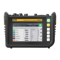
Parker Service Master CONNECT Operating Manual (278 pages)
Brand:
Parker
| Category:
Measuring Instruments
| Size: 4 MB
Table of Contents
Deutsch
3
Table of Contents
3
1 Gerätebeschreibung
9
Bestimmungsgemäße Verwendung
10
Fehlgebrauch
10
Konformität
11
Lieferumfang
11
2 Sicherheitsinformationen
12
Darstellung
12
Sicherheitsstufen
12
Warnhinweise
13
Grundlegende Warnhinweise
14
Handlungsbezogene Warnhinweise
16
Fachpersonal
17
3 Aufbau und Funktion
18
Übersicht
19
Funktion und Ausstattungsmerkmale
20
Anschlüsse
21
Parker Can/Fremd-CAN
22
D-In/D-Out F1/F2
24
Anschlüsse - Inputmodule
25
4 Inputmodule
26
Inputmodul Einstecken
27
Inputmodul Analog (SCMI-600-01)
28
Inputmodul CAN (SCMI-600-02)
30
5 Inbetriebnahme
32
Akku Aufladen
32
Gerät Ein- und Ausschalten
33
Sensoren Anschließen
34
Aufsteller Verwenden
35
Gerät Montieren
36
6 Bedienung
38
Grundlagen
38
Das Gerät Bedienen
39
Bildschirmaufbau
42
Statusleiste
43
Schnellstartmenü
44
Bildschirmtastaturen
46
Menübereich
48
Optionen
50
Werte Zurücksetzen
51
Messansichten
52
Ansicht Liste 6
53
Ansicht Liste 12
54
Manometeransicht
55
Kurvenansicht
56
Messungen Analysieren
59
Kanäle Bearbeiten (Edit Channels)
62
Status einer Messung
65
Messvarianten
66
Start/Stopp (Start/Stop)
67
Datenlogger (Data Logger)
68
Punktemessung (Point Measurement)
70
Trigger
72
Trigger Logic (Trigger Logic)
75
Fast-Messung (Fast Measurement)
78
Messung Durchführen
81
Projektverwaltung
82
SPC (Service Project Container)
82
SPC (Service Project Container) Erstellen
84
Hauptmenü (Menu)
87
Dateimanager (File Manager)
88
Dateien Verwalten
89
Sensoren (Sensors)
90
Can X
92
Can y
92
D-In/D-Out F1/F2
94
6.10.4 Inputmodul a und B
98
Rechenkanäle (Calculating Channels)
100
Verbindungen (Connections)
102
Netzwerke (Wireless & Networks)
103
Remote-Desktop Verbindung (Remote Desktop)
104
Einstellungen (Settings)
105
Gerät (Device)
106
Benutzer (User)
108
6.12.3 System
109
6.12.4 Service
110
Informationen (Information)
111
Datensicherung (Backup) Durchführen
112
Datensicherung (Backup) Wiederherstellen
114
7 Störungsabhilfe
116
Gerät Neustarten
117
Gerät auf Werkseinstellungen Zurücksetzen
118
Firmware Aktualisieren
120
8 Verpackung und Transport
122
9 Reinigung und Wartung
123
Reinigung
123
Wartung
123
Reparatur
124
10 Entsorgung
125
11 Technische Daten
126
Gerätevarianten
126
Mechanische Daten
126
Bildschirmdaten
126
Stromversorgung (Extern)
127
Stromversorgung (Intern)
127
11.3.3 Speicher
127
Eingänge
128
11.4.1 CAN-Bus
128
11.4.2 D-In/D-Out/F1/F2
128
11.4.3 Rechenkanäle
128
Schnittstellen
129
11.5.1 USB-Device
129
11.5.2 USB-Host
129
11.5.3 Lan
129
11.5.4 Wlan
129
Inputmodule Analog (SCMI-600-01)
130
11.6.1 Anschlüsse SC-Sensoren
130
11.6.2 Anschluss Fremdsensor
130
Inputmodul-CAN (SCMI-600-02)
131
12 Anhang
132
Zubehör
132
Technische Normen
132
Maßzeichnungen
133
Typenschild
136
Zertifikate
136
Abbildungsverzeichnis
138
Fig. 1 the Parker Service Master CONNECT
138
English
141
1 Product Description
147
Intended Use
148
Improper Use
148
Conformity
149
Equipment Supplied
149
2 Safety Information
150
Notation
150
Safety Levels
150
Warnings
151
Basic Warnings
152
Safety-Related Warnings
154
Technical Personnel
155
3 Design and Function
156
Overview
157
Fig. 2 Overview
157
Functions and Features
158
Connections
159
Fig. 3 Connections
159
Parker CAN / External CAN
160
Fig. 4 Connection Port, CAN X / CAN y
160
D-In/D-Out F1/F2
162
Fig. 5 Connection Port, D-IN/D-OUT
162
Connection Ports - Input Modules
163
Fig. 6 Connection Port, Input Module
163
4 Input Modules
164
Inserting the Input Module
165
Fig. 7 Insert the Input Module
165
Analog Input Module (SCMI-600-01)
166
Fig. 8 Analog Input Module (SCMI-600-01)
166
Fig. 9 PIN Assignment, Analog Input Module (SCMI-600-01)
167
CAN Input Module (SCMI-600-02)
168
Fig. 10 CAN Input Module (SCMI-600-02)
168
Fig. 11 PIN Assignment, CAN Input Module (SCMI-600-02)
169
5 Starting up
170
Charging the Battery
170
Switching the Device on and off
171
Connecting the Sensors
172
Fig. 12 Connect the Sensors
172
Using the Stand
173
Fig. 13 Using the Fold-Out Stand
173
Mounting the Device
174
Fig. 14 Assembling the Holder
174
6 Operation
176
Basic Factors
176
Operating the Device
177
Screen Design
180
Fig. 15 Screen Layout
180
Status Bar
181
Quick Start Menu
182
Fig. 16 Quick Start Menu
182
Screen Keyboards
184
Fig. 17 Screen Keyboard, Characters and Digits
184
Fig. 18 Screen Keyboard, Simple Arithmetic Operations
185
Fig. 19 Screen Keyboard, Advanced Mathematical Calculations
185
Menu Area
186
Options
188
Fig. 20 Options Menu in Measurement Views
188
Fig. 21 Options Menu in the File Manager
188
Resetting Values
189
Measurement Views
190
List 6 View
191
Fig. 22 List 6 View
191
List 12 View
192
Fig. 23 List 12 View
192
Manometer View
193
Fig. 24 Manometer View
193
Trend Graph View
194
Fig. 25 Trend Graph View
194
Fig. 26 Curve Tools
195
Analyzing the Measurements
197
Fig. 27 Trend Graph View, Analyzing Measurements
197
Fig. 28 Curve Tools
198
Edit Channels
200
Fig. 29 Edit Channels
200
Fig. 30 Edit Channels, Adjust Parameters
202
Measurement Status
203
Measuring Methods
204
Fig. 31 Measuring Methods
204
Start/Stop
205
Data Logger
206
Fig. 32 Data Logger, Settings
207
Point Measurement
208
Fig. 33 Point Measurement), Settings
209
Trigger
210
Fig. 34 Trigger, Settings
211
Fig. 35 Trigger, Settings
212
Trigger Logic
213
Fig. 36 Trigger Logic, Settings
215
Fast Measurement
216
Fig. 37 Fast Measurement, Settings
218
Completing a Measurement
219
Project Management
220
SPC (Service Project Container)
220
Fig. 38 SPC (Service Project Container)
221
Creating an SPC (Service Project Container)
222
Fig. 39 Create an SPC (Service Project Container)
222
Fig. 40 Create an SPC (Service Project Container)
223
Fig. 41 Create an SPC (Service Project Container)
224
Menu
225
Fig. 42 Menu
225
File Manager
226
Fig. 43 File Manager
226
Managing Files
227
Fig. 44 Manage Files
227
Sensors
228
Fig. 45 Sensors
228
Can X
230
6.10.2 Can y
230
Fig. 46 CAN-Y Connection Port, Settings
231
D-In/D-Out F1/F2
232
Fig. 47 Connection D-IN/D-OUT F1/F2, Settings
232
6.10.4 Input Modules a and B
236
Fig. 48 Input Module, Settings
236
Fig. 49 PIN Assignment of Sensors Without Sensor Detection
237
6.10.5 Calculating Channels
238
Fig. 50 Calculating Channels
239
Connections
240
Fig. 51 Connections
240
6.11.1 Wireless & Networks
241
Fig. 52 Wireless & Networks
241
6.11.2 Remote Desktop
242
Fig. 53 Remote Desktop
242
Settings
243
Fig. 54 Settings
243
6.12.1 Device
244
Fig. 55 Device
245
6.12.2 User
246
Fig. 56 User
246
6.12.3 System
247
Fig. 57 System
247
6.12.4 Service
248
Fig. 58 System
248
6.12.5 Information
249
Fig. 59 Information
249
Creating a Backup
250
Restoring a Backup
252
7 Troubleshooting
254
Restarting the Device
255
Fig. 60 Restarting the Device
255
Resetting the Device to Its Default Settings
256
Updating the Firmware
258
8 Packaging and Transporting
260
9 Cleaning and Maintenance
261
Cleaning
261
Maintenance
261
Repairing
262
10 Disposal
263
11 Technical Data
264
Device Model
264
Mechanical Data
264
Touchscreen Data
264
Power Supply (External)
265
Power Supply (Internal)
265
11.3.3 Memory
265
Inputs
266
CAN Bus
266
D-In/D-Out/F1/F2
266
Calculation Channels
266
Interfaces
267
11.5.1 USB Device
267
11.5.2 USB Host
267
11.5.3 Lan
267
Wifi (WLAN)
267
Analog Input Modules (SCMI-600-01)
268
11.6.1 Connections, SC Sensors
268
11.6.2 Connection, External Sensor
268
Can Input Module (SCMI-600-02)
269
12 Appendix
270
Accessories
270
Technical Standards
270
Dimensional Drawings
271
Rating Plate
274
Certificates
274
List of Figures
276
Advertisement
Advertisement
Related Products
Parker ServiceJunior
Parker SensoControl ServiceJunior
Parker Serviceman Level One
Parker Serviceman Level Two
Parker SensoControl ServiceJunior Series
Parker ServiceJunior SCJN Series
Parker Serviceman Plus
Parker SensoControl ServiceJunior SCJR-230-02
Parker SensoControl Serviceman SCM-150 Series
Parker SCJN-1000-03
Parker Categories
Controller
Control Unit
Industrial Equipment
Dryer
DC Drives
More Parker Manuals
Login
Sign In
OR
Sign in with Facebook
Sign in with Google
Upload manual
Upload from disk
Upload from URL