Sign In
Upload
Manuals
Brands
Park Air Systems Manuals
Antenna
NORMARC 7000 ILS
Park Air Systems NORMARC 7000 ILS Manuals
Manuals and User Guides for Park Air Systems NORMARC 7000 ILS. We have
1
Park Air Systems NORMARC 7000 ILS manual available for free PDF download: Instruction Manual
Park Air Systems NORMARC 7000 ILS Instruction Manual (70 pages)
M-ARRAY GLIDE PATH ANTENNA SYSTEM
Brand:
Park Air Systems
| Category:
Antenna
| Size: 3 MB
Table of Contents
Section 1
13
Table of Contents
13
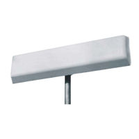
Figure 1-1 Kathrein Glide Path Antenna Element 713 316 B
17
Antenna Distribution Unit
17
General Information
17
Antenna System
17
Antenna Element
17
Antenna Mast
18
Standard Mast
18
Figure 1-2 Kathrein Glide Path Antenna Element Radiation Patterns at MID-Band
18
Frangible Mast
19
Performance and Radiation Patterns
19
Figure 1-3 CSB, SBO and Clearance Field Distribution
19
Antenna System Signal Distribution
20
Figure 1-4 DDM Distribution for a 3° Glide Path
20
Table 1-1 NORMARC 3545 Antenna System Signal Distribution
20
Antenna Element
21
Antenna Distribution Unit DIA 346B
21
General
21
Frangible Antenna Mast
21
Standard Antenna Mast
21
Technical Specifications
21
Monitoring Combining Unit MOA 338D
22
Technical Description
23
Mechanical Antenna Assembly
23
Standard Mast
23
Frangible Mast
23
Antenna Element
23
Figure 2-1 Block Diagram of DIA 346B Antenna Distribution Unit
24
Hybrids
24
Power Distribution Components
24
Electrical Description
24
Mechanical Description
24
Antenna Distribution Unit - DIA 346B (ADU)
24
Adjustable Power Dividers
25
Figure 2-2 3Db Hybrid (180°-Type)
25
Figure 2-3 Adjustable Power Divider
25
Adjustable Phase Shifter
26
Monitoring Combining Unit - MOA 338D (MCU)
26
Mechanical Description
26
Electrical Description
26
Displacement Sensitivity
26
Near Field Monitoring
27
Monitoring Combining Unit
29
Antenna Distribution Unit
29
Electrical - Antenna System
29
Operation
29
Mechanical - Antenna System
29
Maintenance
31
Preventive Maintenance
31
Antenna System
31
The Glide Path Beam Forming Area (BFA)
31
Control of Vegetation in BFA
31
Figure 4-1 M-Array Glide Path BFA
31
Snow Removal from BFA
32
Corrective Maintenance
32
Discussion
33
Conditions
33
Required Test Equipment
33
Objective
33
General
33
Adjustments Procedure
33
Alignments Procedure
34
Mechanical Alignments
34
Antenna Element Forward Shift
34
Antenna Height
34
Antenna Element Offset
34
Figure 5-1 Forward Slope (FSL) and Antenna Forward Shift
34
Electrical Alignments - Cable Phasing
35
CSB and SBO Cables
35
CSB/SBO Phasing
35
Figure 5-2 Lateral Antenna Offset (NM3545)
35
Figure 5-3 Cable Phasing Measurement Set-Up
35
Figure 5-4 Phase and Amplitude Transfer Measurement Set-Up
36
Antenna Cable Lengths
36
Phase and Amplitude Transfer Measurement
36
Preliminary SBO Power Adjustment
36
Antenna Return Loss
37
Phase and Amplitude Check of Antenna Distribution Unit DIA 346B
37
Preparation
37
Table 5-1 Standard Antenna Distribution Values
37
Procedure (Measurement and Verification Only)
38
Procedure (in Case Parameter Is out of Tolerance Given in Table 5-1)
38
Figure 5-5 Test Set-Up for Antenna Distribution Unit Phase and Amplitude Check
38
Monitoring Combining Unit Adjustments
39
Table 5-2 Plug-In Attenuator Type Versus Forward Slope Angle
39
Adjustments Procedure
40
Near Field Monitor Antenna Position
40
General
40
Near Field Monitor Antenna Position Tolerance
41
Check of Correct Near Field Monitor Antenna Position
41
Figure 5-6 Near Field Monitor Carrier Phase Test Set-Up
42
Appendix 1: Calculation of Antenna Parameters
45
Glide Path
47
Section 2
48
Beam Forming Area
49
Definitions
49
General
49
Calculation of FSL
50
Calculation of Terrain Slopes
50
Coordinate System
50
Calculation of SSL
51
Calculation of Ils Glide Path Antenna Positions and Feeds
53
Common Parameters
53
Forward Slope
53
Side Slope
53
Antenna Forward Shift
54
Vertical Antenna Element Spacing
54
Vertical DDM Distribution on Course Line (Far Field)
54
Antenna Feeds
55
Ratio between Largest CSB and SBO Feed Amplitudes
55
Lateral Antenna Offset between Upper and Lower Antenna
56
Near Field Monitor Position
56
NM 3543 (Null Reference) ILS Glide Path System
56
Antenna Heights and Near Field Monitor
57
Lateral Antenna Offset between Upper and Lower Antenna
57
NM 3544 (Sideband Reference) ILS Glide Path System
57
Antenna Heights and Near Field Monitor
58
Lateral Antenna Offset between Antennas
58
NM 3545 (M-Array) ILS Glide Path System
58
Appendix 2: Attached Drawings
59
Advertisement
Advertisement
Related Products
Park Air Systems 3545
Park Air Systems Categories
Radio
Transceiver
Antenna
Transmitter
More Park Air Systems Manuals
Login
Sign In
OR
Sign in with Facebook
Sign in with Google
Upload manual
Upload from disk
Upload from URL