Sign In
Upload
Manuals
Brands
Panasonic Manuals
HDTV
TH-65PV500B
Panasonic TH-65PV500B Manuals
Manuals and User Guides for Panasonic TH-65PV500B. We have
2
Panasonic TH-65PV500B manuals available for free PDF download: Service Manual, Operating Instructions Manual
Panasonic TH-65PV500B Service Manual (194 pages)
Digital High Definition Plasma Television
Brand:
Panasonic
| Category:
HDTV
| Size: 33.99 MB
Table of Contents
Lead of Wiring
2
How to Enter SERVICE
2
Packing Exploded Views
2
Table of Contents
3
Applicable Signals
5
Safety Precautions
6
General Guidelines
6
Touch-Current Check
6
Prevention of Electro Static Discharge (ESD) to
7
Electrostatically Sensitive (ES) Devices
7
About Lead Free Solder (Pbf)
8
Service Hint
9
Plasma Panel Replacement Method
10
Remove the
10
Remove the P-Board
10
Remove the PB-Board
11
Remove the D-Board
11
Remove the Rear Terminal Cover
12
Remove the Metal Frame
12
Remove the XV-Board (PV500 Only) and DV-Board
12
Remove the DG-Board
12
Remove the H-Board and TA-Board
13
Remove the PA-Board
13
Remove the Z-Board
13
Remove the Fan (Middle/R)
13
Remove the Fan (Big and Middle/L)
14
Remove the Fan (SC)
14
Remove the Fan (SS)
14
Remove the SU-Board
14
Remove the SD-Board
15
Remove the SC-Board
16
Remove the SS2-Board
16
Remove the SS3-Board
16
Remove the SS-Board
16
Remove the C1-Board
17
Remove the C2-Board
17
Remove the C3-Board
17
Remove the H3-Board (L, R)
17
Remove the C4-Board
18
Remove the C6-Board
18
Remove the Front Bracket
19
Remove the G-Board
19
Remove the GK-Board
19
Remove the GS-Board and SD-Module
19
Remove the K-Board and the S-Board
20
Remove the Plasma Panel Section from the Front Frame
21
(Glass)
21
Remove the Reinforcement Angles (L, R) and the
21
Connection Plate (A, B, C, D)
21
Replace the Plasma Panel (Finished)
21
Location of Lead Wiring
22
Lead of Wiring
22
Lead of Wiring
23
Self Check
25
Power LED Blinking Timing Chart
26
No Power
27
No Picture
28
Local Screen Failure
29
Service Mode Function
30
How to Enter SERVICE
30
Option Description
32
Adjustment Procedure
34
Driver Set-Up
34
Initialization Pulse Adjust
35
Printed Circuit Board) Exchange
36
Adjustment Volume Location
36
Test Point Location
36
Adjustment
37
PAL Panel White Balance Adjustment
37
1080I White Balance Adjustment
38
Sub Bright Adjustment
39
ABL Adjustment
39
TEXT Vref Auto Adjustment
40
Hotel Mode
41
Conductor Views
43
P-Board
43
PA-Board
47
PB-Board
48
H-Board
49
TA-Board
51
G-Board
52
H3, GK, GS and K-Board
53
DG-Board
54
DV-Board
56
XV-Board (PV500B)
57
Z-Board
59
D-Board
60
C1-Board
63
C2-Board
64
C3-Board
65
C4-Board
66
C5-Board
67
C6-Board
68
SC-Board
69
SU-Board
72
SD-Board
73
SS-Board
74
S, SS2 and SS3-Board
77
Block and Schematic Diagram
79
Schematic Diagram Notes
79
Main Block Diagram
80
P-Board (1 of 2) Block Diagram
81
P-Board (2 of 2) Block Diagram
82
P-Board (1 of 3) Schematic Diagram
83
P-Board (2 of 3) Schematic Diagram
84
P-Board (3 of 3) Schematic Diagram
85
PA-Board Block Diagram
86
PA-Board Schematic Diagram
87
PB-Board Block and Schematic Diagram
88
H and TA-Board Block Diagram
89
G, GK, GS, and K-Board Block Diagram
90
H-Board (1 of 2) Schematic Diagram
91
H-Board (2 of 2) Schematic Diagram
92
G-Board Schematic Diagram
93
GK, K and TA-Board Schematic Diagram
94
GS-Board Schematic Diagram
95
DG-Board (1 of 2) Block Diagram
96
DG-Board (2 of 2) Block Diagram
97
DG-Board (1 of 13) Schematic Diagram
98
DG-Board (2 of 13) Schematic Diagram
99
DG-Board (3 of 13) Schematic Diagram
100
DG-Board (4 of 13) Schematic Diagram
101
DG-Board (5 of 13) Schematic Diagram
102
DG-Board (6 of 13) Schematic Diagram
103
DG-Board (7 of 13) Schematic Diagram
104
DG-Board (8 of 13) Schematic Diagram
105
DG-Board (9 of 13) Schematic Diagram
106
DG-Board (10 of 13) Schematic Diagram
107
DG-Board (11 of 13) Schematic Diagram
108
DG-Board (12 of 13) Schematic Diagram
109
DG-Board (13 of 13) Schematic Diagram
110
DV-Board Block Diagram
111
DV-Board Schematic Diagram
112
XV-Board Block Diagram (PV500B)
113
XV-Board (1 of 5) Schematic Diagram (PV500B)
114
XV-Board (2 of 5) Schematic Diagram (PV500B)
115
XV-Board (3 of 5) Schematic Diagram (PV500B)
116
XV-Board (4 of 5) Schematic Diagram (PV500B)
117
XV-Board (5 of 5) Schematic Diagram (PV500B)
118
Z and H3-Board Block Diagram
119
Z and H3-Board Schematic Diagram
120
D-Board Block Diagram
121
D-Board (1 of 6) Schematic Diagram
122
D-Board (2 of 6) Schematic Diagram
123
D-Board (3 of 6) Schematic Diagram
124
D-Board (4 of 6) Schematic Diagram
125
D-Board (5 of 6) Schematic Diagram
126
D-Board (6 of 6) Schematic Diagram
127
C1, C2, C5 and C6-Board Block Diagram
128
C2, C3, C4 and C5-Board Block Diagram
129
C1-Board (1 of 2) Schematic Diagram
130
C1-Board (2 of 2) Schematic Diagram
131
C2-Board (1 of 2) Schematic Diagram
132
C2-Board (2 of 2) Schematic Diagram
133
C3-Board (1 of 2) Schematic Diagram
134
C3-Board (2 of 2) Schematic Diagram
135
C4-Board (1 of 2) Schematic Diagram
136
C4-Board (2 of 2) Schematic Diagram
137
C5-Board (1 of 2) Schematic Diagram
138
C5-Board (2 of 2) Schematic Diagram
139
C6-Board (1 of 2) Schematic Diagram
140
C6-Board (2 of 2) Schematic Diagram
141
SC, SU and SD-Board Block Diagram
142
SC-Board (1 of 3) Schematic Diagram
143
SC-Board (2 of 3) Schematic Diagram
144
SC-Board (3 of 3) Schematic Diagram
145
SU-Board (1 of 2) Schematic Diagram
146
SU-Board (2 of 2) Schematic Diagram
147
SD-Board (1 of 2) Schematic Diagram
148
SD-Board (2 of 2) Schematic Diagram
149
SS, S1, SS2 and SS3-Board Block Diagram
150
SS-Board (1 of 2), S1, SS2 and SS3-Board Schematic Diagram
151
SS-Board (2 of 2) Schematic Diagram
152
Parts Location & Mechanical Replacement Parts List
153
Parts Location
153
Packing Exploded Views
154
Packing Exploded Views
156
Mechanical Replacement Parts List
157
Electrical Replacement Parts List
159
Replacement Parts List Notes
159
Electrical Replacement Parts List
160
Advertisement
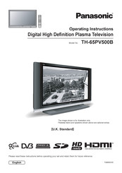
Panasonic TH-65PV500B Operating Instructions Manual (60 pages)
Digital High Defi nition Plasma Television
Brand:
Panasonic
| Category:
Plasma TV
| Size: 9.22 MB
Table of Contents
Table of Contents
2
Important Safety Notice
3
Safety Precautions
4
Maintenance
5
Accessories
6
Fitting Remote Control Batteries
6
Cable Binding Instructions
7
How to Open the Front Cover
7
Quick Start Guide
8
Basic Controls: Front Panel and Remote Control
11
Using the on Screen Displays
12
Picture Menu
13
Sound Menu
14
Setup Menu
15
Tuning Menu - Overview
16
Tuning Menu - Programme Edit
17
Adding / Deleting a Programme Channel
17
Moving a Programme Channel
17
Renaming a Programme Channel
18
Locking a Programme Channel
18
Copying Programme Information to a Recording Device
18
Tuning Menu - Auto Setup
19
Tuning Menu - Manual Tuning
20
Manual Tuning (Via Front Panel)
20
Owner ID
21
Shipping Condition
22
DVB Setup Menu - Overview
23
Timer Programming Menu
24
Profi le Edit Menu
26
Child Lock Menu
27
DVB Tuning Menu
28
DVB System Setup
29
Common Interface Module Menu
30
System Update Menu
31
TV Guide - Electronic Programme Guide (EPG)
32
Information Banner
33
Subtitles on / off
33
Q-Link
34
Aspect Controls
35
Still
36
Multi Window
37
PC Mode
38
Card Operations
40
VCR / DVD Operation
48
Teletext Operation
49
Connections
52
How to Connect the Headphones / AV3 Terminals
52
How to Connect the Audio Output Terminals
53
How to Connect the AV1 / 2 / 4 Scart Terminals
53
How to Connect the Component Input Terminals
53
How to Connect the HDMI Input Terminal
54
How to Connect the PC Input Terminal
55
Troubleshooting
56
DVB Troubleshooting
57
Scart and S-Video Terminal Information
58
Input Signal that Can be Displayed
58
Specifi Cations
59
Advertisement
Related Products
Panasonic TH-65PV500E
Panasonic TH-32LRU30
Panasonic TH-32LRH30U
Panasonic TH-55LRU50
Panasonic TQB2AA0775
Panasonic VIERA TC-P54G20
Panasonic TC-L47E50-1
Panasonic TC-55EZ950C
Panasonic TC-77EZ1000C
Panasonic TC-65EX750X
Panasonic Categories
Air Conditioner
Camcorder
TV
Digital Camera
Cordless Telephone
More Panasonic Manuals
Login
Sign In
OR
Sign in with Facebook
Sign in with Google
Upload manual
Upload from disk
Upload from URL