Sign In
Upload
Manuals
Brands
Panasonic Manuals
DVR
AJ-YA750P
Panasonic AJ-YA750P Manuals
Manuals and User Guides for Panasonic AJ-YA750P. We have
2
Panasonic AJ-YA750P manuals available for free PDF download: Service Manual
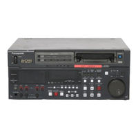
Panasonic AJ-YA750P Service Manual (303 pages)
DVCPRO Studio VTR, Component Serial I/F Board
Brand:
Panasonic
| Category:
DVR
| Size: 13 MB
Table of Contents
Introduction
2
Specifications
2
Safety Precautions
3
General Guidelines
3
Leakage Current Cold Check
3
Leakage Current Hot Check
3
Contents
5
Operating Instructions
6
General and Features
7
Features
8
Front Panel
8
Dial Jog/Shuttle
8
Menu-Driven Setup
8
Front Panel Top Section
9
Front Panel Centre Section
9
Front Panel Bottom Section
12
Controls and Their Functions
13
Connector Area
13
Connections When One Unit Is Used
15
Connections When 2 Units Are Used
15
Connections with Editing Controller
16
Connections for Adjusting Video Output Signals
16
Tapes
17
Switching on the Power/Inserting the Cassette
17
Stop/Stand by Mode
18
Recording
18
Still Timer Setting
18
Setting Video/Audio Input Signals
18
Playback
19
Jog/Shuttle Modes
19
Jog Mode
19
Shuttle Mode
19
Manual Editing
20
Preroll
20
Automatic Editing
21
Switch Settings and Adjustments
21
When the Unit Is Used as the Recorder
21
When the Unit Is Used at the Player
21
Select the Editing Mode
22
Entering the Edit Points
22
Match Frame Processing Function
22
Negative Duration Function
22
Checking the Edit Points
23
Modifying the Edit Points
23
Resetting both the Edit in and out Points
23
Resetting the Either the Edit in or out Points
23
Executing Automatic Editing
24
Preview
24
Postroll
24
Retry Function
24
Split Editing
25
Review
25
Video Output Signal Adjustments
26
Setup
26
Default Settings
26
Changing the Settings
26
System Menu
27
Changing the File
27
User Menu
28
Recording Internal/External Time Codes
35
Reproducing the Time Code/User Bit
35
Setting the Internal Time Code
35
Superimpose Screen
36
Servo Reference
36
Characters Displayed
36
Display Position
36
Servo Reference Setting Tables
37
Audio V Fade Function
37
During Playback or Special Playback
37
During Recording or Editing
37
Printed Circuit Board
38
Rack Mounting
38
Connector Signals
39
Video in
39
Video out
39
Audio in
39
Video Head Cleaning
40
Condensation
40
Maintenance
41
Mechanical Adjustment
41
Maintenance Parts Chart
43
Sensor Layout
45
Servicing Fixtures & Tools
46
Boards Location
49
Alignment Tapes
50
DVCPRO Alignment Tape
50
Recommended Test and Service Equipment
51
Ntsc
51
Pal
51
Disassembly Method
52
Remove of Top Panel
52
Removal of Bottom Panel
52
Removal of Front Panel
52
Removal of Front Loading Unit
53
Removal of Power Supply Unit
53
Removal of Cylinder Unit
54
Removal of Mechanism Unit
54
Removal of Fun Motor Unit
55
Manual Tape Eject
56
Cleaning Procedures
58
Cleaning of Head Chips
58
Cleaning of A/C Head
58
Cleaning of Pinch Roller and Capstan
58
Mechanism Adjustment
59
Name of Tape Transportation
59
Cassette Height Position Pin Adjustment
60
Pinch Solenoid Position Adjustment
61
Main Brake Torque Confirmation
62
Post Height Pre-Adjustment
63
A/C Head Height Pre Adjustment
64
Tension Arm Adjustment Procedures
65
Tension Arm Offset Voltage Adjustment
66
Tension Arm Neutral Position Adjustment
67
No Tape Loading Procedures
67
Tension Arm PLAY Voltage Adjustment
68
Tension Arm REV Voltage Confirmation
69
Tension Arm Tension Regulator Spring Adjustment
70
REV Tension Confirmation
71
Tension Confirmation
72
Post Coarse Adjustment
72
Play Mode Tension Confirmation
73
Reverse Tension Confirmation
74
Tape Pass Adjustment Procedures
75
Tape Pass Adjustment and Tape Pass Limit Confirmation
76
Envelope Waveform Adjustment
77
A/C Head Tilt Adjustment
78
A/C Head Height Adjustment
79
A/C Head Azimuth Adjustment
80
Confirmation of Envelope of REV, REW, FF Mode
81
Confirm of PLAY Start Envelope
82
Envelope Confirmation
82
S4 Tension Post Height Adjustment
83
Tape Limitation Confirmation Procedures
84
REV Tape Pass Limit Adjustment
85
Play Tape Pass Limit Confirmation
87
REV Tape Pass Limit Confirmation
88
FF, REW Tape Pass Limit Confirmation
89
Loading Tape Pass Limit Confirmation
90
A/C Head Confirmation Procedures
91
A/C Head Tilt Confirmation
92
A/C Head Height Confirmation
93
A/C Head Self Recording Level Confirmation
94
A/C Head Azimuth Confirmation
95
A/C Head Horizontal Position Adjustment
96
A/C Head Screw Lock Tight Grew
97
T3 Post, T4 Post Lock Tight Grew
97
LISTA Adjustment
98
LISTA Connection
99
Setting of LISTA Servo Adjustment Menu
100
LIST Sensitivity Adjustment
101
LISTA Sensitivity Detection
102
LISTA Linearity Adjustment
103
LISTA Waving Measurement
104
LISTA Data Saving
105
LISTA Sensitivity Adjustment
106
PB Head
106
LISTA Consumer DV Compatibility Playback Confirmation
107
Playback Envelope Confirmation
108
Self Recording Playback Envelope Confirmation
109
Major Mechanism Parts Replacement and Adjustment
110
Cylinder Unit Replacement
110
Adjustment Flow Chart after Cylinder Unit Replacement
111
T1 Guide Position Adjustment
111
How to Making the Loading Condition
111
Adjustment Flowchart after Drum Unit & Mech Chassis Replacement
112
A/C Head Replacement
113
Adjustment Flowchart after A/C Head Adjustment
114
Connection of A/C Head
114
Supply and Take up Reel Table Replacement
115
Supple and Take up Unit Replacement
115
Connection of Mecha I/F P.C. Board
116
Removal of S & T Reel Rotor Unit
116
Install of S & T Reel Rotor Unit
116
Loading Motor Unit Replacement
117
Pinch Arm Unit Replacement
117
Supply and Take up Brake Arm Unit Replacement
118
Mode Select Switch Unit Replacement
118
Cleaning Arm Unit Replacement
119
Removal of Cleaner Roller Unit
119
Adjust of T1 Guide
119
Pinch Solenoid Replacement
120
Supple Brake Solenoid Replacement and Adjustment
120
Take up Brake Solenoid Replacement and Adjustment
121
Brake Solenoid Adjustment
121
Removal of Take up Brake Solenoid
121
MIC Rail Unit Replacement
122
S1 Post Loading Arm Unit Replacement and Adjustment
122
Removal of S1 Post Loading Arm Unit
123
T1 Boat Unit Replacement
124
T1 Loading Arm Unit Replacement and Adjustment
124
Cleaner Solenoid Replacement and Adjustment
124
Cleaner Solenoid Position Adjustment
125
Removal of Cleaner Solenoid
125
Cleaner Roller Position Adjustment
126
S5 Post Base Unit Replacement
126
Reel Drive Motor Unit Replacement
126
Tension Arm Unit Replacement
127
Tension Arm Adjustment Flowchart
127
Main Cam Gear Replacement
128
M-Stopper Solenoid Replacement and Adjustment
128
L-M Release Angle Unit Replacement
129
Slide Rod Unit Replacement and Adjustment
129
T4 Post Phase Adjustment
130
Removal of Slide Red Unit
130
Removal of Reel Drive Arm Unit
130
Phase of T4 Post
130
Electrical Adjustments
131
Servo Circuit Adjustment
133
Motor Torque Offset Adjustment
133
PG Shifter Adjustment
133
System Control
134
Super Impose Position Adjustment
134
CUE P.C. Board
135
Initial Setting of CUE Adjustment
135
CTL Erase/Cue Erase Current Adjustment
135
CUE Bias Current Adjustment
136
CUE PB Level Adjustment
136
Noise Cancel Adjustment
137
CUE REC/PB Level Coarse Adjustment
137
CUE REC/PB Frequency Characteristic Adjustment
138
CUE REC/PB Level Adjustment
138
Rf
139
Pre Eq Adjustment
139
RF AMP PB Phase Adjustment
139
Eq
140
Preparation of EQ Adjustment
140
PLL Lock Adjustment
141
PLL Latch Phase Coarse Adjustment
141
PLL Slice Level Coarse Adjustment
142
EQ Adjustment
142
PLL Latch Phase Fine Adjustment
143
PLL Slice Level Fine Adjustment
144
Viterbi A/D Input Level Adjustment
144
PLL Latch Phase Adjustment
145
PLL Slice Level Adjustment
146
PLL Lock Confirmation
148
Consumer DV Viterbi Confirmation
151
How to Confirm the Error Rate
151
REC P.C. Board
152
REC Current, Frequency Characteristic Adjustment
152
Item Parameter
152
Rotary Erase Current Adjustment
153
Video out P.C. Board
154
Preparation for Video out Adjustment
154
Carrier Balance Adjustment
155
Sync Level Adjustment
155
Composite Set up Level Adjustment
156
System Sub-Carrier Phase Adjustment
156
System Horizontal Phase Adjustment
157
Burst Phase Adjustment
157
Burst Level Adjustment
158
Burst Phase Position Adjustment
158
Composite y Level Adjustment
159
Composite y Frequency Adjustment
159
Vector Adjustment
160
Component y Frequency Adjustment
161
Component y Level Adjustment
161
Component Pb Level Adjustment
162
Component Pr Level Adjustment
162
Component Y-Pb Timing Adjustment
163
Component Y-Pr Timing Adjustment
163
Video Phase Adjustment
164
V_IN P.C. Board
165
Preparation for Video in Adjustment
165
Component y Signal Level Adjustment
166
Composite Output Level Adjustment
168
Composite Y/C Timing Adjustment
168
Block Diagrams
169
Rec/Pb
182
The Record System
182
Playback System
182
Block Diagram
183
PB Head Mode
193
REC Head Mode
193
Rf Amp
195
REC Signal
195
The Playback Signal of REC HEAD
195
Head Buffer
196
Signal Flow
196
Rotary Erase
196
Record
196
Head Buffer Block Diagram
197
Service Information
199
Auto off Error Message
201
Auto off Check Point Table
206
Service Menu Information
218
Set up the Service Menu
218
Servo Adjust
219
EQ Adjust
220
How to Load or Save the Adjustment Value
221
RF Adjust
222
Video Adjust
223
Audio Adjust
223
How to Reset the Hour Meter
224
How to Confirm the Soft Version
225
Exploded Views & Parts List
227
Casing Parts Assembly
230
Front Panel Assembly
232
Chassis Frame Assembly
234
Rear Panel Assembly
236
Mechanical Chassis Assembly
238
Sub Chassis Assembly
242
Packing Parts Assembly
246
Advertisement
Panasonic AJ-YA750P Service Manual (361 pages)
DVCPRO Studio VTR, Component Serial I/F Board
Brand:
Panasonic
| Category:
DVR
| Size: 20 MB
Advertisement
Related Products
Panasonic AJ-YAD850G
Panasonic AJ-SPD850MC
Panasonic AJ-D750E
Panasonic AJ-D750EN
Panasonic AG-CPDIOCRUP
Panasonic AG-MDR15P
Panasonic AG-MDR15E
Panasonic AG-CPD15P
Panasonic AG-CPD10CRUP
Panasonic AG-CPD20P
Panasonic Categories
Air Conditioner
Camcorder
TV
Digital Camera
Cordless Telephone
More Panasonic Manuals
Login
Sign In
OR
Sign in with Facebook
Sign in with Google
Upload manual
Upload from disk
Upload from URL