Sign In
Upload
Manuals
Brands
PairGain Manuals
Network Hardware
HiGain-ETSI RS UTU 712
PairGain HiGain-ETSI RS UTU 712 Manuals
Manuals and User Guides for PairGain HiGain-ETSI RS UTU 712. We have
1
PairGain HiGain-ETSI RS UTU 712 manual available for free PDF download: Manual
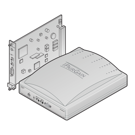
PairGain HiGain-ETSI RS UTU 712 Manual (80 pages)
RATE SELECTABLE HDSL LINE AN DESKTOP UNITS
Brand:
PairGain
| Category:
Network Hardware
| Size: 2.29 MB
Table of Contents
Table of Contents
3
Overview
9
Rate Selectable HDSL Unit Firmware
9
EMU Firmware Compatibility
10
Application Interface
10
Figure 1. Transport of Customer Video Service to an Nx64K Serial Network
10
Table 1. Rate Selectable HDSL Unit Characteristics
10
HDSL Technology
11
Transmission Ranges
11
Table 2. Transmission Ranges with ETSI Noise
11
Front and Rear Panel Components
12
Figure 2. UTU-712 Line Unit Front Panel
12
Figure 3. ETU-762 Desktop Unit Front Panel
12
Table 3. Line and Desktop Unit Front Panel Components
13
Table 4. Line and Desktop Unit Front Panel LED Indications
14
Figure 4. ETU-762 Desktop Unit Rear Panel
15
Table 5. ETU-762 Desktop Unit Rear-Panel Components
15
Higain-ETSI Product Compatibility
16
Table 6. Higain-ETSI Product Compatibility
16
Specifications
17
Functional Description
19
Major Components
19
Figure 5. Line and Desktop Unit Functional Block Diagram
19
Nx64K Serial Data Port
20
HDSL Interface
20
System Timing Circuits
20
Figure 6. Transmission of Serial Data in Manual Mode and Nx64K Auto Mode
20
Processor
21
Figure 7. Data Port Transmit Timing
21
On-Board Power Supply Modules
22
Single-Pair Rate Selectable Applications
22
Figure 8. Single-Pair Rate Selectable HDSL Video Conferencing Application
22
Figure 9. Single-Pair Rate Selectable HDSL Frame Relay Application
22
Hot Swapping
23
Performance Monitoring and History
23
Alarms
23
Table 7. Monitored HDSL Transmission and Interface Performance Parameters
23
Loopbacks
24
Table 8. HDSL Transmission and Application Interface Alarms
24
Figure 10. Loopback Operations
25
Table 9. Loopbacks Selected at Front Panel Pushbutons and Console Screens
25
BER Testing
26
Table 10. Loopback Equivalents
26
Inspection, Safety, and Equipment Repair
27
Inspection
27
Safety
27
Equipment Repair
27
Installation and Startup
28
UTU-712 Line Unit Installation
28
Figure 11. Installing the UTU-712 Line Unit
28
ETU-762 Desktop Unit Installation
29
HDSL Startup and Synchronization
29
System Configuration
30
Maintenance Terminal Connection
30
Figure 12. UTU/ETU Console Port and Maintenance Terminal Connector Pinouts
30
Modem Connection
31
Figure 13. Connecting a Maintenance Terminal to a Line Unit
31
Logging on
32
Figure 14. Logon Password Screen
32
Figure 15. Console Screen Menu Bar
32
Console Screen Menu Structure
33
Figure 16. Console Screen Menu Structure
33
Table 11. Console Screen Menus
34
Reading and Navigating Menus
35
Figure 17. Items in Console Screen Status Bar
35
Table 12. Console Screen Status Bar Displays
35
Table 13. Console Screen Navigation Keys
36
Config Menu Options
37
Figure 18. Console Screen Config Menu
37
Table 14. Config Menu Options and Recommended Order of System Configuration
37
Configure Terminal Settings
38
Figure 19. Config Terminal Settings Menu
38
Configure Date and Time
39
Figure 20. Config Date and Time Menu
39
Change Password
40
Figure 21. Config Change Password Menu
40
Configure Circuit ID
41
Figure 22. Config Circuit ID Menu
41
Configure System Settings
42
Figure 23. Config System Settings Menu
42
Table 15. Fields and Options in Config System Settings Menu
43
Configure LTU and NTU Interfaces
44
Figure 24. Config LTU Interface Menu
44
Figure 25. Config NTU Interface Menu
44
Table 16. Fields and Options in Config LTU and Config NTU Interface Menus
45
Table 17. V.35/V.36/X.21 Output Control Signal Operation
45
Configure Alarms
46
Figure 26. Config Alarms Menu
46
Figure 27. Config Alarms LTU Interface Menu
47
Figure 28. Config Alarms NTU Interface Menu
47
Figure 29. Config Alarms HDSL Span 1 Menu
48
Table 18. Fields in Config Alarms LTU and Config Alarms NTU Interface Menus
48
Set to Factory Defaults
49
Figure 30. Set to Factory Dflts Screen
49
Table 19. Fields in Config Alarms HDSL Span 1 Menu
49
Logging off
50
Table 20. Factory Default System Settings
50
Viewing Status
51
Main Console Screen
51
Figure 31. Main Console Screen
51
Table 21. Reading the Main Console Screen
51
Table 22. Fields in Main Console Screen
52
Monitor Menu
53
Figure 32. Monitor Menu
53
Monitor LTU Interface Screen
54
Figure 33. Monitor LTU Interface Screen
54
Table 23. Fields in Monitor LTU and Monitor NTU Interface Screens
54
Monitor NTU Interface Screen
55
Figure 34. Monitor NTU Interface Screen
55
Monitor HDSL Span 1 Screen
56
Figure 35. Monitor HDSL Span 1 Screen
56
Table 24. Fields in Monitor HDSL Span 1 Screen
56
History Menu
57
Figure 36. History Menu
57
History LTU and NTU Interface Screens
58
Figure 37. History LTU Interface Menu
58
Figure 38. History NTU Interface Menu
58
Figure 39. LTU Interface Alarm History Screen
59
Table 25. Alarm History Data
59
HDSL Span Performance History Screens
60
Figure 40. History HDSL Span 1 Menu
60
Figure 41. 24 Hour History Screen for HDSL Span 1
60
Figure 42. 7 Day History Status Screen for HDSL Span 1
61
Figure 43. Alarm History Status Screen for HDSL Span 1
62
Table 26. HDSL Span Alarm History Data
62
Clear History Screens
63
Inventory Screen
63
Figure 44. Inventory Screen
63
Table 27. Inventory Screen Data
64
Testing
65
Figure 45. Test Menu Screen
65
Table 28. Test Menu Options
66
Table 29. BER Section of Test Menu
66
Firmware Download Utility
67
Figure 46. ETSI Firmware Download Utility Menu
67
Table 30. ETSI Firmware User Selectable Download Menu Options
68
Table 31. Navigating the ETSI Firmware Download Menu
68
Reference Information
69
ETU-762 Connector Pinouts
69
Table 32. D9F HDSL Line Connector Pinouts
69
Table 33. D25F Data Port Connector Pinouts
69
ECA-800 Connector Adapter (DB25M to M34F for V.35)
70
Figure 47. ECA-800 DB25M to M34F (V.35) Connector Adapter, Part Number 150-1470-01
70
Table 34. ECA-800 DB25M to M34F (V.35) Connector Adapter Pinouts
70
ECA-801 Connector Adapter (DB25M to DB15F for X.21)
71
Figure 48. ECA-801 D25M to DB15F (X.21) Connector Adapter, Part Number 150-1470-01
71
Table 35. ECA-801 DB25M to DB15F (X.21) Connector Adapter Pinouts
71
ECA-802 Connector Adapter (DB9M to RJ-45)
72
Figure 49. ECA-802 DB9M to RJ-45 Connector Adapter, Part Number 150-1472-01
72
Table 36. ECA-802 DB9M to RJ-45 Connector Adapter Pinouts
72
ECA-804 Connector Adapter (DB9M to Four-Position Terminal Block)
73
Figure 50. ECA-804 DB9M to Four-Position Terminal Block Connector Adapter, Part Number 150-1474-01
73
Table 37. ECA-804 DB9M to Four-Position Terminal Block Connector Adapter Pinouts
73
Pairgain Regional Sales Offices
74
Table 38. Pairgain Regional Sales Offices
74
Product Support
75
Technical Support
75
Warranty
75
Internet Access
76
Compliance
76
Table 39. Minimum Creepage and Clearance Distances
76
Abbreviations
77
Advertisement
Advertisement
Related Products
PairGain HiGain-ETSI RS ETU-762
PairGain UTU-722
PairGain HiGain ETSI UTU-814
PairGain 150-1111-81
PairGain 150-1111-84
PairGain 150-1111-85
PairGain 150-1140-51
PairGain 150-1140-53
PairGain 150-1140-55
PairGain 150-1141-05
PairGain Categories
Network Hardware
Remote Control
Touch terminals
Switch
Computer Hardware
More PairGain Manuals
Login
Sign In
OR
Sign in with Facebook
Sign in with Google
Upload manual
Upload from disk
Upload from URL